NX CIP Safety Connection Guide to KUKA KRC5 KSS version 5.1
Table of Contents
Purpose and ScopeTesting EquipmentReferenced Documents Downloadable FilesProcedureStandard Ethernet/IP ConnectionCIP Safety ConnectionPre-compiled EDS filesGenerating Safety EDS FileInstalling CIP Safety EDS fileSetting Target TUNIDCIP Safety and Standard IO ConnectionSample ProgramPurpose and Scope
The purpose of this document is to demonstrate a connection guide to a KUKA KRC5 running KSS 5.1 with standard I/O, CIP Safety and CIP Safety + standard I/O configurations
Testing Equipment
KUKA KRC5 KSS 5.1
Sysmac Studio 1.47
NX-SL5700 V1.3
NX-CSG320 V1.01
Alternative OMRON Equipment (Not tested)
Sysmac Studio >1.45
NX-SL5500
NX102
Referenced Documents
| Manual Name | Cat. No. |
| Technical Supplement - Kuka KRC4 4.1 CIP Safety | |
| CIPSafetyDemo_Kuka_5.1 | |
| KRC5CipSafety (EDS File) | |
| KRC5EtherNetIP (EDS File) | |
| NJ/NX-series CPU Unit Built-in Ether-Net/IP Port User’s Manual | W506 |
| Safety Network Controller Units NX-SL5___ User's Manual | Z395 |
Downloadable Files
Contents
-Sample Program
-Kuka 2 Byte EDS file
-Kuka 8 Byte EDS file
-OMRON generated safety EDS file 2 Byte
-OMRON generated safety EDS file 8 Byte
Procedure
Standard Ethernet/IP Connection
1. Configure IP address of both devices to be on the same subnet (Refer to NJ/NX-series CPU Unit Built-in Ether-Net/IP Port User’s Manual).
a. Go to Built-in EtherNet/IP Port settings under Configurations and Setup in the Multiview Explorer tree.
b. Select TCP/IP Settings.
2. Import KRC5EtherNetIP EDS file into Sysmac Studio (Refer to NJ/NX-series CPU Unit Built-in Ether-Net/IP Port User’s Manual).
a. Go to EtherNet/IP Settings under Tools.
b. Right click on Target Devices located in Toolbox container, then click Display EDS Library.
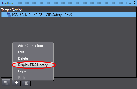
c. Click install and navigate to the EDS files, once added they will show in the EDS Library.

3. Register required network variables to match the length defined in the KRC5 (Refer to NJ/NX-series CPU Unit Built-in Ether-Net/IP Port User’s Manual)
a. Define variables in Global Variables with Data Type and size to match the connection requirements.
b. Assign the variables Network Publish type as Input or Output.

c. In the Tag Set tab in EtherNet/IP Connection Settings, click Registration All.

d. If the Global Variables had their Network Publish set correctly, they will show up in the Tag Set Registration Setting window. Tick all required variables and press Register.
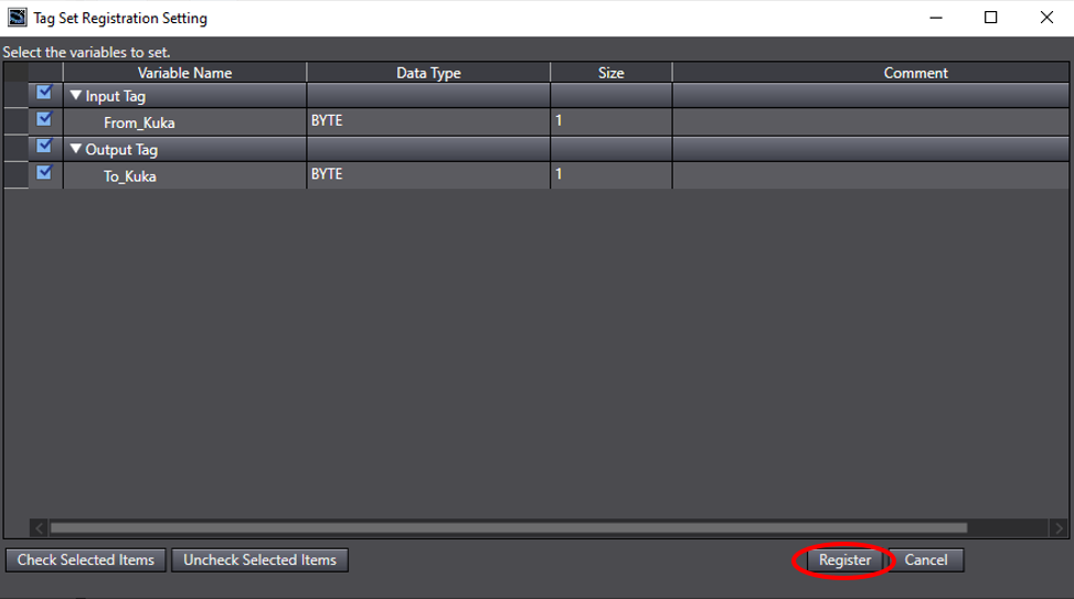
e. This will automatically map them in the Tag Set.
4. Register the tag set and assign target device using the imported EDS file to selected port within “EtherNet/IP Connection Settings” under tools (Refer to NJ/NX-series CPU Unit Built-in Ether-Net/IP Port User’s Manual).
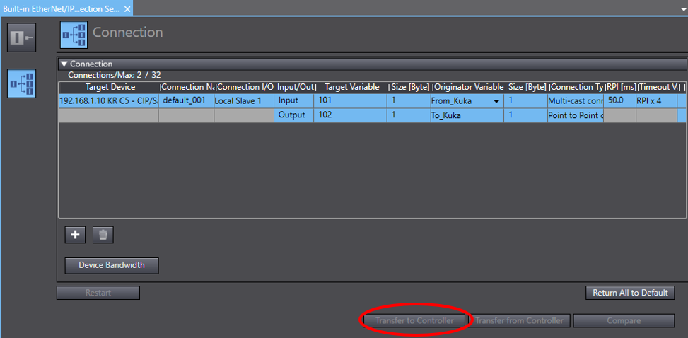
a. Create a new connection to the KRC5 by pressing the + symbol under Target Devices.
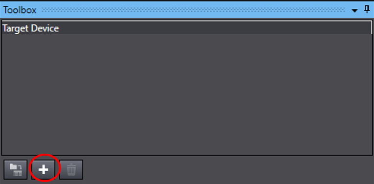
b. Fill in required IP address and the type of EDS file required and Add.

c. The new connection will be added.
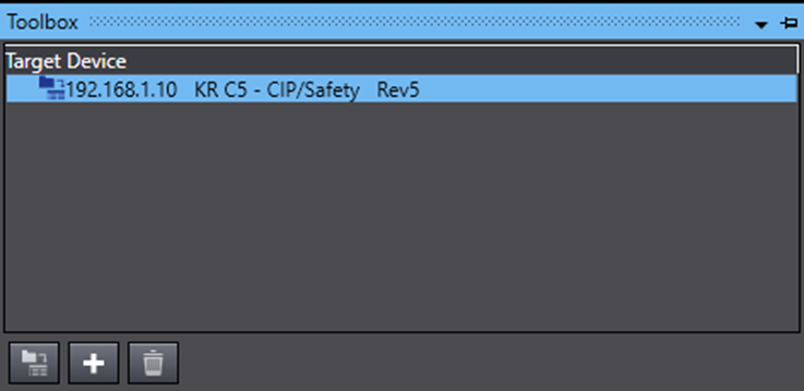
d. Add a new connection selecting the new connection that was made.
e. The Target Variable and Size is defined in the robot EtherNet/IP setup (Note: the size must also match the variables created, otherwise they will unable to be selected. Double click on size to edit).
f. Once the Size matches the registered variables they will be selectable. The Connection is now complete, click Transfer to Controller to implement the connections.
CIP Safety Connection
Pre-compiled EDS files
2 Byte EDS File: KR C5 2 Bytes - CIPSafet_322A98ED
8 Byte EDS File: KR C5 8 Bytes - CIPSafet_3B77D32D
Generating Safety EDS File
1. Please follow Safety Network Controller Units NX-SL5___ User's Manual on how to generate a safety EDS file within Sysmac Studio.
2. Assembly Instance can be found within the KUKA software (See example below). Device Information can be found within the KRC5CipSafety EDS file.


Installing CIP Safety EDS file
1. Configure IP address of both devices to be on the same subnet (Refer to NJ/NX-series CPU Unit Built-in Ether-Net/IP Port User’s Manual).
2. Install required EDS file for your safety I/O requirements (Follow Safety Network Controller Units NX-SL5___ User's Manual).
3. Create variables for CIP Safety device within the I/O Map.
Setting Target TUNID
The KRC5 requires the TUNID to be set from the originator, in this case the NX-SL5# unit.
Single Target
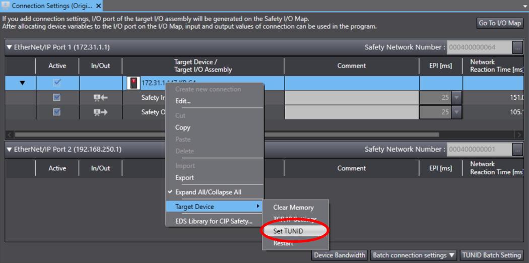
To set a single target’s TUNID (Safety Network Number) you can right click on the target device -> “Target Device” -> “Set TUNID”. This will transfer the targets unique Safety Network Number to it. This number has to be cleared first if it had a previous number with another safety network.
Multiple Targets
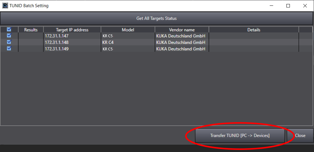
1. To set multiple targets TUNID (Safety Network Number) click “TUNID Batch Setting”.

2. Select “Transfer TUNID [PC -> Devices]”. This will transfer all the targets unique Safety Network Number. These numbers must be individually cleared first if it had a previous number with another safety network. (See Setting Target TUNID - Single Target)
CIP Safety and Standard IO Connection
To be able to create a CIP Safety and standard IO connection the KRC5CipSafety EDS needs to be used in the Ethernet/IP Connection Settings, instead of KRC5EtherNetIP EDS File.
Follow CIP Safety connection and Standard IO connection above for configuration.’
Sample Program
A connection sample program is provided using the test equipment above, with a 1 byte EtherNet/IP connection and 8 Byte CIP Safety connection.
To open this file, firstly a blank project needs to be opened up and the provided CIP Safety EDS files needs to be installed.
1. Go to Communications -> Safety -> EtherNet/IP Safety Connection Settings -> Connection Settings (Originator).
2. Right Click under a port and select EDS Library for CIP Safety.
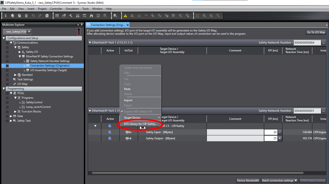
3. Either a new EDS file can be generated from above instructions or by clicking install the pre-generated ones can be used.

4. Once installed the sample program will be able to be opened without any errors.
| Date | 08/11/2021 |
| Revision Number | 1.00 |
| Authors | Joshua Hem |