3G3MX2 Quick Start Guide

Written by Arlo D'Cruz
Updated at February 18th, 2026
CORE SETUP PARAMETERS
Motor Nameplate Settings
- H003 - Motor KW
- H004 - No of Motor Poles, (1500rpm = 4 poles, 3000rpm = 2 poles etc)
- A003 - Base frequency, (Motor Nameplate freq, 50Hz for AU/NZ)
- A004 – Maximum frequency (Sets max range of Speed Reference)
- A044 – V/f Characteristics (Set to 00 unless high start torque required.)
See the following setup guide - https://store.omron.co.nz/knowledge-base/setting-up-sensorless-vector-control-for-mx2s
Motor Protection
- b012 - Motor Thermal Model, set to nameplate Amps
At this point the Motor is controllable from the Buttons on the front of the Drive.
CONTROL SETUP
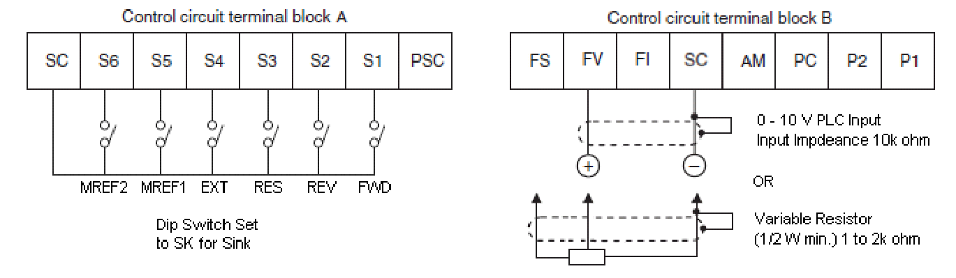
Option A – 2 wire Control with 0-10V Ref
- A001 – Frequency Reference Selection = 01 (Terminal)
- A002 – Run Command Selection = 01 (Terminal)
- C001 - C007 = Default
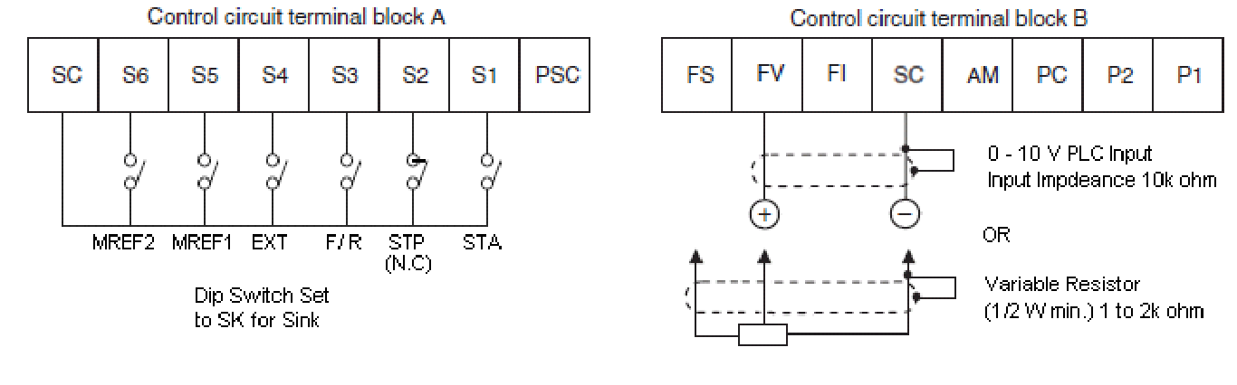
Option B – 3wire Control with 0-10V Ref
- A001 – Frequency Reference Selection = 01 (Terminal)
- A002 – Run Command Selection = 01 (Terminal)
- C001 – Multifunction Input 1 Selection = 20 STA (3-wire Start)
- C002 – Multifunction Input 2 Selection = 21 STP (3-wire Stop) (N.C)
- C003 – Multifunction Input 3 Selection = 22 F/R (3-wire Fwd / Rev)
- C004 - Unused = 255 No function
- C005 - Unused = 255 No function
- C006 - Unused = 255 No function
- C007 - Unused = 255 No function
Useful Parameters
F001 – Output Frequency Setting if run off Digital Operator (A001 – 02)
F002 – Acceleration Time
F003 – Deceleration Time
B037 – Parameter display (Set this to 00 for full access to all parameters)
B083 – Carrier Frequency (Allows adjustment to eliminate any audible motor noise)
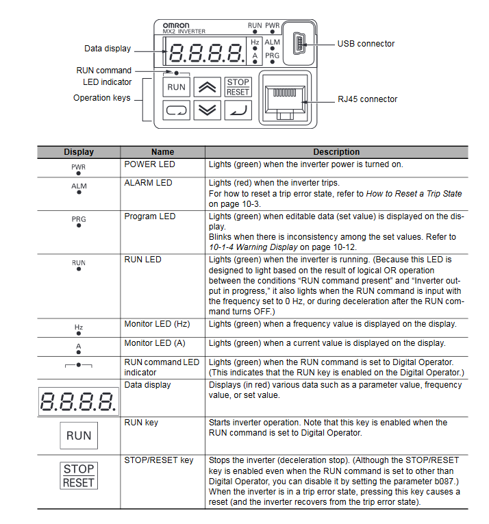
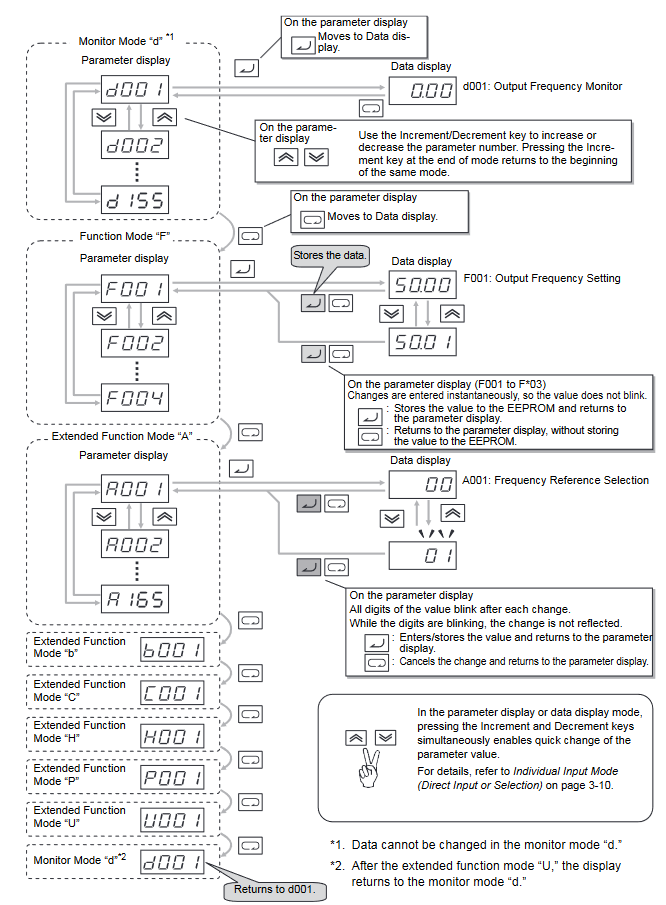
Navigation
Key Description
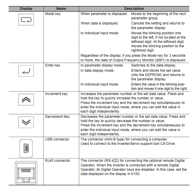


Parameter Transition

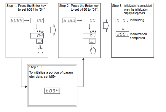
Factory Reset
To initialize the inverter, follow the steps below.
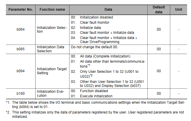
- Select initialization mode in b084.
- Set initialization target in B094.
- Set 01 in b180.
- The process is complete when D001 is displayed.
Info
Remember that it is impossible to undo the initialization once you press the Enter key ( ) to execute parameter initialization, with the Initialization Execution (b180) set to 01.
- When the Soft Lock Selection (b031) is set to prohibit changes of the initialization-related parameters (b084, b094, b180), the initialization cannot be executed. Change the Soft Lock
Selection (b031) to enable the initialization. For details on Soft Lock Selection, refer to 7-6-1 Soft Lock Function (SFT) on page 7-54. - When parameter initialization is in progress, the inverter will ignore the RUN command even if it is ON. Enter the RUN command again after completion of the initialization process.