3G3MX2 is not reaching expected speed

Written by Daniel Heslewood
Updated at May 2nd, 2025
During set up of the 3G3MX2 series of VSD's, a common issue is that the drive does not reach the expected frequency that has been set.
This can happen for a few reasons but the most common reason we see is that the Frequency Reference Selection (A001) has been set incorrectly, or left as default. By default this is set to 02: Digital Operator. This setting uses the frequency set in F001 as its reference, by default F001 is set to 6Hz for safety reasons.
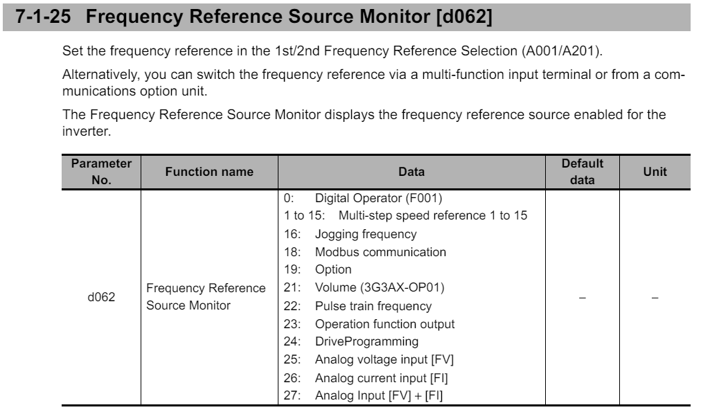
The MX2 series can dynamically change it's frequency reference depending on how the drive is configured, sometimes this overrides the frequency which has been set. The quickest way to see the current source of frequency reference, is to view the parameter d062: Frequency Reference Source Monitor. The value of this parameter identifies where the reference is being set from. The frequency correlation chart determines the priority at which the frequency is referenced.
Once you have identified the frequency reference the drive is using, it may be easier to identify other parameters which may be limiting the output frequency of the inverter.
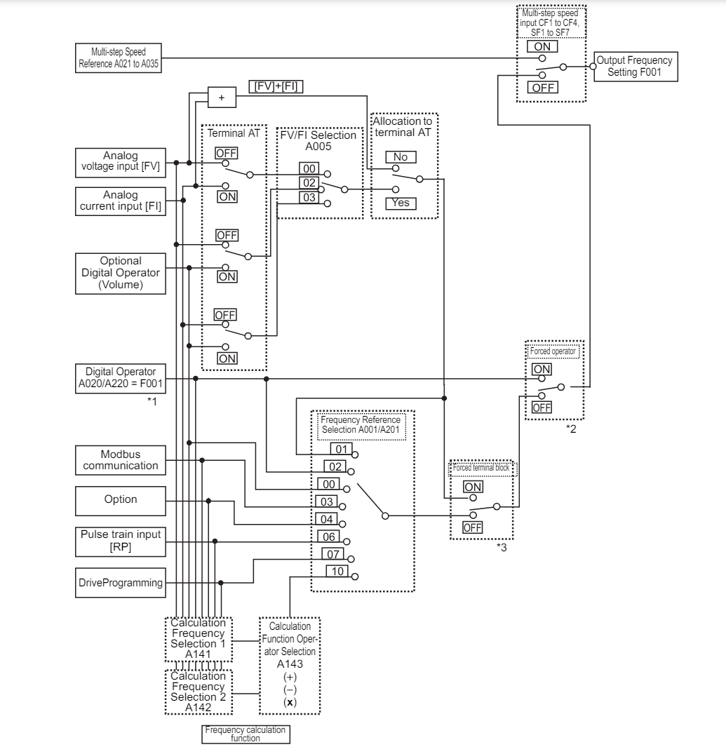
Frequency Reference Correlation Chart
The following chart can be useful to identify why the drive has selected one frequency reference over another. One of these parameters may be taking priority over the intended reference selection.
For example, if any of the Multi-step speed inputs CF1-CF4, SF1 to SF7 are ON, the drive will use the Multi-step Speed reference set in A021 to A035 as priority over any other input.
When Using The Multi-Function Inputs
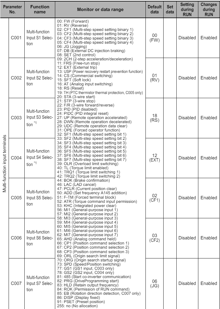
The Multi-function inputs are commonly used for various reasons. By default the Multi-function Inputs S5-S6 are set to Multi-Step Speed setting (CF1-CF2). If these inputs are being used but the parameters have not been changed, then when either of these inputs become TRUE, the drive will use the Multi-step Speed Reference set in A021 as priority over any other frequency reference. This can be rectified by modifying the parameter for the respective input. Either to the correct function for the use case, or to 255: no (No allocation). The full list of parameters for the Multi-Function inputs can be found below.
Multi-Function Terminal Parameters
Speed Relating To Analog Input
When using an Analog signal for speed control, you can see the live value of the Analog input by viewing parameters d130: Analog Voltage Input FV Monitor and, d131: Analog Current Input FI Monitor. Both values are expressed as a bit data type ranging from 0-1023 where:
- Voltage at terminal FV (d130), a value of 1023 = 10.9V.
- Current at terminal FI (d131), a value of 1023 = 23.2mA.
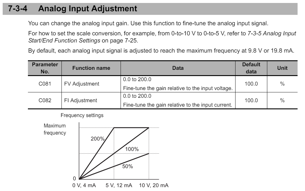
By default, each analog input signal is adjusted to reach the maximum frequency ad 9.8V or 19.8mA. Therefore you should expect to see a value of at least 873 in d131 or, 919 in d130 if the analog input is receiving it's full value.
If the monitor value is below these values, and the sensor is healthy, you can try adjusting the parameters below to increase the gain at the analog input.
Overcurrent Suppression
By default, overcurrent suppression is enabled to limit the output current to the motor.
You cannot monitor if this function is activated, instead you will need to monitor the output current in d002 and see if this is approximately 180% of the rated current.
Setting this parameter to 00: Disabled, would be a quick way to determine if this is being activated. This won't prevent the overcurrent event from happening and will likely cause the drive to trip on overcurrent (E01, E02, E03).
If you are able to determine that overcurrent suppression is activating, one solution would be to increase the Acceleration Time set in F002.

Overload Limit
The inverter monitors the motor current during acceleration or constant speed operation and, if the set overload limit level is reached, decreases the output frequency automatically according to the overload limit parameter. This function is useful to prevent the occurrence of an overcurrent trip due to an excessive torque during acceleration or rapid load fluctuations during constant speed operation.
By default, the 1st overload limit selection b021 is set to 01: Enabled during acceleration and constant speed.
If for example the drive never reaches full speed, setting b021 to 02: Enabled during constant speed, would allow the drive to temporarily ignore the limit level set in b022, until the drive has reached constant speed.
If you suspect that the overload limit is preventing the drive from reaching its set frequency you can try making the following adjustments.
- Increase the Acceleration time in F002.
- Increase the Overload limit level in b002.


Please refer to our 3G3MX2 Quick Start Guide for further information on setup and core parameters.