How to use the IR/DR areas for Indirect Addressing
1. Introduction
Indirect addressing is not a function like LD, MOV, TIM, etc. It is the concept of substituting a pointer for a direct memory address in an instruction, and then manipulating the pointer to change the ultimate memory location being used.
Indirect addressing allows the programmer to use one memory location (or a combination of memory locations) as a pointer to another memory location.
By manipulating the value of the pointer, an operation can be performed on a memory address that varies based on the ladder program. Indirect addressing can be used for searching, sorting, lookup tables, recipe manipulation, and many more functions.
There are 3 different ways to perform indirect addressing. These are BCD indirect addressing, Binary indirect addressing, and IR/DR indirect addressing. This article focuses on the third option, IR/DR indirect addressing.
The concept of using IR/DR indirect addressing is similar to BCD and Binary indirect addressing, but the mechanism is different. Index Registers (IR) and Data Registers (DR) are used to store the internal memory address of almost any memory location in the PLC (CIO, HR, WR, DM, EM, T/C, AR, and TK). One substantial difference between IR/DR indirect addressing and @/* DM/EM addressing is that IR/DR indirect addressing can be used to address Channel or Bit information. This allows the programmer to indirectly address different bits within one or across multiple channels.
Since the addresses are stored in the IR/DR areas, this means they can be used to pass addresses to a function block. The user can pass a numeric address value to a FB which can then be translated to an address.
2. IR/DR Explained
Index Registers (IR)
Manipulating IRs: Index Registers (IR) are double wide memory areas. Double wide Binary instructions can be used to manipulate them. The value of IRs can be used in double wide comparison instructions. Remember, do not place a ‘,’ in front of the IR to address the value of the IR itself i.e. MOVL #10000 IR8 loads #10000 into IR8. MOVL #10000 ,IR8 moves #10000 to the memory location currently held in IR8. IR registers can be used to reference memory areas with addresses longer than a single word.
Data Registers (DR)
Manipulating DRs: Data Registers are single word binary registers. They can be manipulated with single wide binary commands (MOV, ++, --, XCG,+, -, etc). DR areas are usually used to store offset values which can be added to the IR channel address.
3. Referencing
Referencing is the process of storing an address inside of the IR/DR areas for later use. There are two main methods that we refer to here as implicit and explicit referencing. Each channel (memory area) on the PLC has a unique address which can be passed to the IR/DR areas for indirect addressing. You can write the address implicitly or explicitly.
Implicit Address Writing
You may implicitly write an address to the IR/DR area using a MOVR instruction. The example below shows how you might move the address D10 to IR0.

Note how D10 has the value #14 stored inside of it. We can indirectly interact with this value by de-referencing IR0 which is explained in the next section.
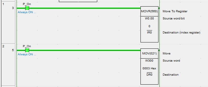
The the IR are can store both the bit address and channel address, but you may want to store these two value separately. The below example shows storing the word address in the IR area and the bit address in the DR area. Note how we use MOVR to move the channel address to IR0 and the MOV to move the offset value to DR0.
Explicit Address Writing
You may also manually set the address that you wish to reference. The PLC manual includes a table showing each memory area and its corresponding address value. The below table shows the memory table for the CJ2.
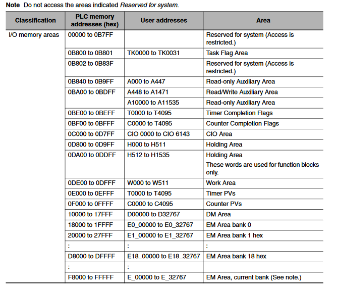
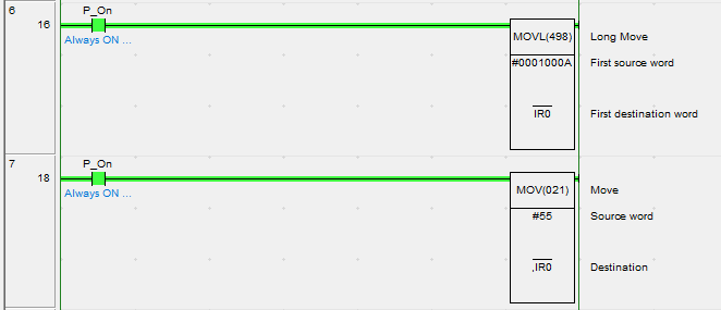
The below example shows how you might write the address D10 to IR0 explicitly. Note that MOVL is used as the IR area is a double channel.

4. De-referencing
De-referencing refers to the process of taking your pointer and resolving it to the address stored inside. This allows you to read or write to/from the address stored inside the IR/DR area.
| Variation | Function | Syntax | Example |
|---|---|---|---|
| Indirect addressing | The content of IRX is treated as the PLC memory address of a bit or word | ,IRX |
Move #100 to the address specified in IR0. If IR0 contains D100 #100 would be moved to D100: MOV #100 ,IR0 |
| Indirect addressing with constant offset | The constant prefix is added to the content of IRX and the result is treated as the PLC memory address of a bit or word. The constant must be between -2048 to 2047. | +/-A,IRX |
Move #100 to the address in IR0 plus 5. If IR0 contains D100 then #100 would be moved to D105: MOV #100 +5,IR0 |
| Indirect addressing with DR offset | The content of the Data Register is added to the content of IRX and the result is treated as the PLC memory address of a bit/word | DRX,IRY |
Move #100 to the address stored in IR0 offset by the value stored in DR0. If IR0 contains D100 and DR0 contains the value 5 then #100 would be moved to D105: MOV #100 DR0,IR0 |
| Indirect addressing with auto-increment | After referencing the content of the IRX as a bit or word the content is automatically incremented by one or two |
Increment by 1: ,IR0+ Increment by 2: ,IR0++ |
Move #100 to D100 then D101. Note that the value stored in IR0 is automatically incremented: MOV #100 ,IR0+ MOV #100 ,IR0 |
| Indirect addressing with auto-decrement | After referencing the content of the IRX as a bit or word the content is automatically decremented by one or two |
Decrement by 1: ,IR0- Increment by 2: ,IR0-- |
Move #100 to D100 then D99. Note that the value stored in IR0 is automatically incremented: MOV #100 ,IR0- MOV #100 ,IR0 |
The below example shows how you might write #55 to the address stored in IR0. In this case IR0 was explicitly written to D10.

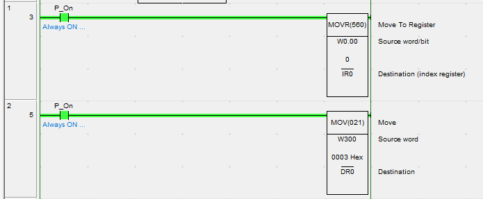
The next example shows how you might write to a bit address with an offset. We write W0.00 to IR0 and the value 3 to the offset area DR0. Calling DR0,IR0 would result in the address W0.03

Other Functions
It is possible to interact with the IR/DR areas with more than just movement instructions. The table below shows a list of supported instructions that you can use with the IR/DR areas.
| Instruction Group | Instruction | Mnemonic |
|---|---|---|
| Data Movement | Move to Register | MOVR |
| Move Timer/Counter PV to Register | MOVRW | |
| Double Move | MOVL | |
| Double Data Exchange | XCGL | |
| Table Data Processing | Set Record Location | SETR |
| Get Record Number | GETR | |
| Increment/Decrement | Double Equal | =L |
| Double Not Equal | <>L | |
| Double Less Than | <L | |
| Double Less Than or Equal | <=L | |
| Double Greater Than | >L | |
| Double Greater Than or Equal | >=L | |
| Double Compare | CMPL | |
| Symbol Math Instructions | Double Signed Binary Add without Carry | +L |
| Double Signed Binary Subtract without Carry | -L |
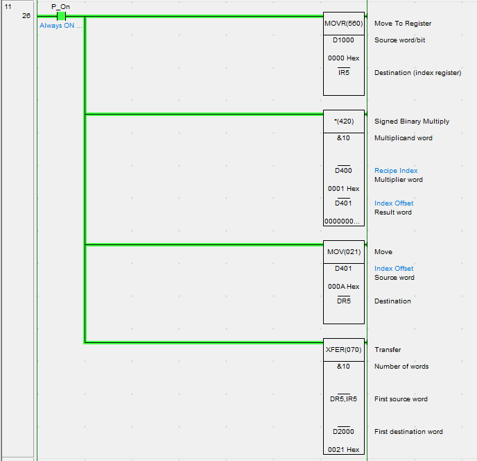
Due to the way the addresses are stored, you cannot use functions such as *L or /L on the IR/DR areas. For functions like recipe selection, we would suggest adding a multiplier to the offset area DR.
The example below shows how you might use the DR and IR areas for recipe selection. D1000 is the starting area of the recipes, D400 is the recipe selection index. An XFER is used to transfer the selected recipe once the index has been set.
