Calculating Memory Offset For CP1W Expansion Boards
Sometimes when a CP1W expansion unit has been added and configured to a PLC, the expansion unit does not read or write data correctly. This is typically because the destination words have been set incorrectly.
This article will help you calculate the correct memory offset and destination word for your configuration.
How many I/O words does my expansion board use?
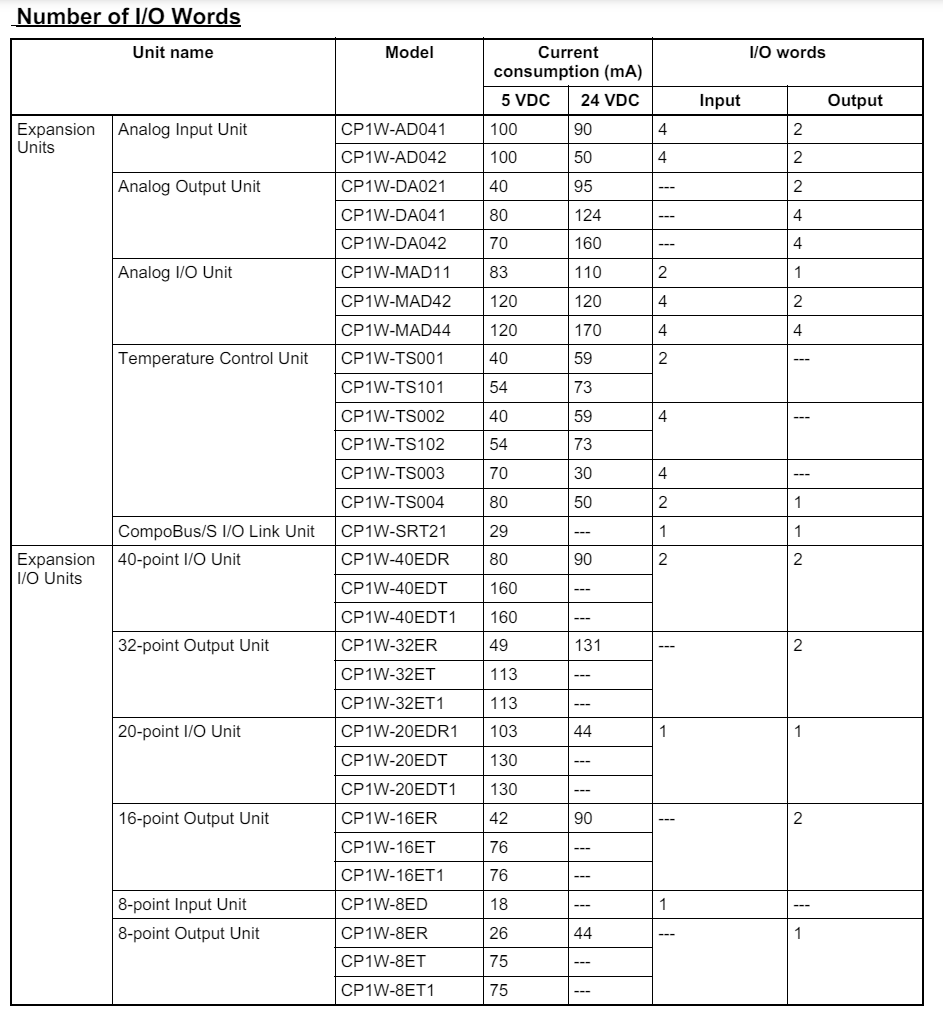
The figure below shows the number of I/O words for all CP1W expansion units. For each unit you will need to take note of both:
- The number of input and output words.
- The position in which the expansion board is connected on your system.

How many I/O words does my PLC use?
Unless stated otherwise, the maximum number of expansion cards that can be added to the unit is 3.
What series of PLC are you using?
What is the Sub-Series of the PLC? CP2E-[?]
How many I/O Points does your PLC have?
CP-series Expansion Units and Expansion I/O Units cannot be connected to this PLC.
CP-series Expansion Units and Expansion I/O Units cannot be connected to this PLC.
Inputs: 2 Words. CIO 0, CIO 1.
Outputs: 2 Words. CIO 100, CIO 101.
Inputs: 2 Words. CIO 0, CIO 1.
Outputs: 2 Words. CIO 100, CIO 101.
Inputs: 3 Words. CIO 0, CIO 1, CIO 2.
Outputs: 3 Words. CIO 100, CIO 101, CIO 102.
How many I/O Points does your PLC have?
Inputs: 2 Words. CIO 0, CIO 1.
Outputs: 2 Words. CIO 100, CIO 101.
Inputs: 2 Words. CIO 0, CIO 1.
Outputs: 2 Words. CIO 100, CIO 101.
Inputs: 3 Words. CIO 0, CIO 1, CIO 2.
Outputs: 3 Words. CIO 100, CIO 101, CIO 102.
How many I/O Points does your PLC have?
CP-series Expansion Units and Expansion I/O Units cannot be connected.
CP-series Expansion Units and Expansion I/O Units cannot be connected.
Inputs: 2 Words. CIO 0, CIO 1.
Outputs: 2 Words. CIO 100, CIO 101.
Inputs: 2 Words. CIO 0, CIO 1.
Outputs: 2 Words. CIO 100, CIO 101.
Inputs: 3 Words. CIO 0, CIO 1, CIO 2.
Outputs: 3 Words. CIO 100, CIO 101, CIO 102.
What is the Sub-Series of the PLC?
Inputs: 2 words. CIO 0, CIO 1.
Outputs: 2 words. CIO 100, CIO 101.
This CPU can have a maximum of 7 Expansion I/O Modules attached.
Inputs: 2 words. CIO 0, CIO 1.
Outputs: 2 words. CIO 100, CIO 101.
This CPU can have a maximum of 7 Expansion I/O Modules attached.
Inputs: 2 words. CIO 0, CIO 1.
Outputs: 2 words. CIO 100, CIO 101.
This CPU can have a maximum of 7 Expansion I/O Modules attached.
What is the Sub-Series of the PLC? CP1L-[?]
How many I/O Points does your PLC have?
Inputs: 1 word. CIO 0.
Outputs: 1 word. CIO 100.
CP1L-EL20[][]-[] can have a maximum of 1 expansion unit.
Inputs: 2 words. CIO 0, CIO 1.
Outputs: 2 words. CIO 100, CIO 101.
Inputs: 2 words. CIO 0, CIO 1.
Outputs: 2 words. CIO 100, CIO 101.
How many I/O Points does your PLC have?
Inputs: 2 words. CIO 0, CIO 1.
Outputs: 2 words. CIO 100, CIO 101.
Inputs: 2 words. CIO 0, CIO 1.
Outputs: 2 words. CIO 100, CIO 101.
Inputs: 3 words. CIO 0, CIO 1, CIO 2.
Outputs: 3 words. CIO 100, CIO 101, CIO 102.
How many I/O Points does your PLC have?
This PLC model does not support expansion units.
Inputs: 1 word, CIO 0
Outputs:1 word, CIO 100
CP1L-L14[][]-[] can have a maximum of 1 expansion unit.
Inputs: 1 word, CIO 0
Outputs:1 word, CIO 100
CP1L-L20[][]-[] can have a maximum of 1 expansion unit.
This content will be shown (depending on) when button above is clicked
How many I/O Points does your PLC have?
Expansion I/O Units cannot be added to this model of PLC.
Expansion I/O Units cannot be added to this model of PLC.
Expansion I/O Units cannot be added to this model of PLC.
Inputs: 2 words. CIO 0, CIO 1.
Outputs: 2 words. CIO 100, CIO 101.
Inputs: 2 words. CIO 0, CIO 1.
Outputs: 2 words. CIO 100, CIO 101.
Inputs: 3 words. CIO 0, CIO 1, CIO 2.
Outputs: 3 words. CIO 100, CIO 101, CIO 102.
This content will be shown (depending on) when button above is clicked
Expansion I/O Units cannot be added to this model of PLC.
Expansion I/O Units cannot be added to this model of PLC.
Inputs: 2 words. CIO 0, CIO 1.
Outputs: 2 words. CIO 100, CIO 101.
Inputs: 2 words. CIO 0, CIO 1.
Outputs: 2 words. CIO 100, CIO 101.
Inputs: 3 words. CIO 0, CIO 1, CIO 2.
Outputs: 3 words. CIO 100, CIO 101, CIO 102.
This content will be shown (depending on) when button above is clicked
Inputs: 1 word. CIO 0.
Outputs: 1 word. CIO 100.
Memory Offset Calculation
Explanation
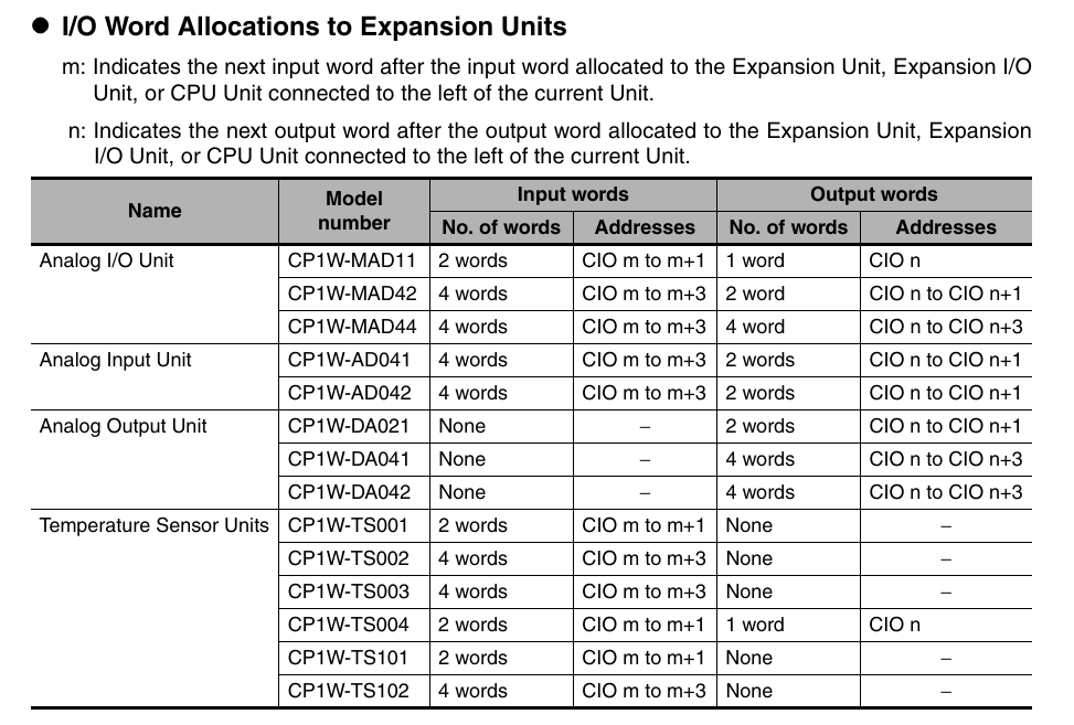
The memory allocation always follows the n+1 convention regardless of whether all of the inputs or outputs of an expansion module are used.
Expansion Units and Expansion I/O Units are allocated I/O bits in the order the Units are connected starting from the CPU Unit. When the power to the CPU Unit is turned ON, the CPU Unit checks for any Expansion Units and Expansion I/O Units connected to it and automatically allocates I/O bits.
More information on configuring analog expansion cards can be found in this article.
From the number of I/O words you have noted previously you can find the total number of words the configuration will use.

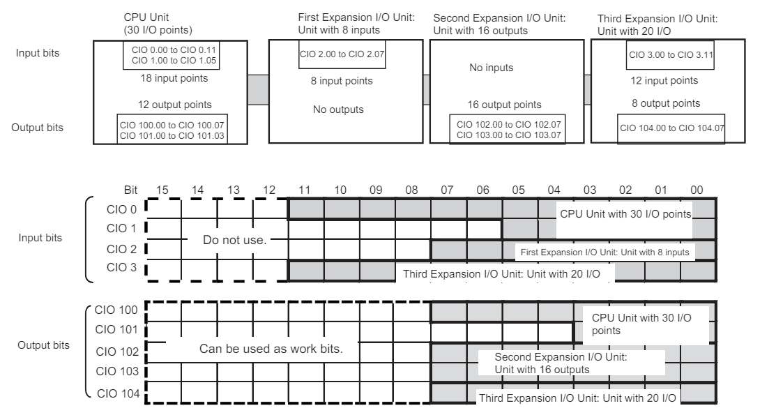
Example 1

The CPU unit uses 2 input words and and 2 output words. CIO 0, CIO 1, CIO 100 and CIO 101 respectively.
The first expansion unit uses only 1 input word, so the destination word for this unit will be CIO 2, the next available word after the CPU unit allocation.
The second expansion unit uses 2 output words. Since the first expansion unit uses no output words, the first destination word is the next available word after the last output word from the CPU, CIO 102. The second destination word will be CIO103.
The third expansion unit uses 1 input word and 1 output word. Since the second expansion unit does not use any input words, the first input destination word of this unit, will be the next available word after the first expansion unit, CIO 3. Likewise the first output destination word will be CIO 104, directly after the previous expansion units last output word.
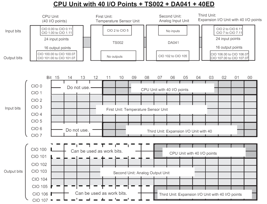
Example 2

This example follows the same convention as example 1, this time using analog input cards and Temperature Sensor Units.