Troubleshooting - Monitor Connected/Disconnected Ethernet/IP Units through CX-Programmer

Written by Tiaan Kemp
Updated at February 27th, 2022
Scenario
You would like to be able to monitor the flags/status of connected Ethernet/IP devices in the network on a CS/CJ processor bus unit through your CX-Programmer project and use the state of the units to trigger alarms in your program.
This will also give you a way to determine if a specific device in terms of IP address has lost connection to a bus.
Solution
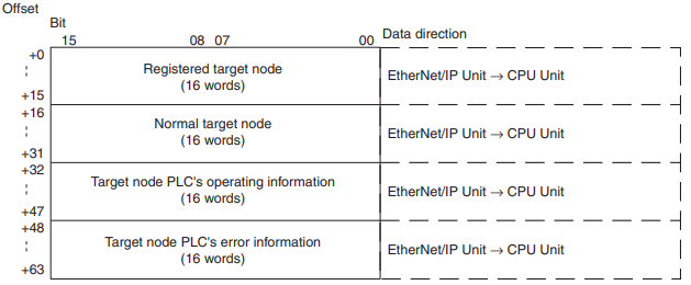
Ethernet/IP Unit Status Area setup:
Default Settings layout:
- Your Status Area is located in the CIO Area by default. Beginning word n = CIO 1500 + (25 × unit number)
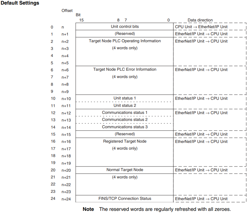
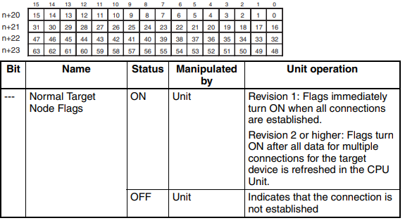
- To view the flags of the connected Nodes (63) with the default settings, this will be located in the Normal Target Node Table (Ethernet/IP Unit to CPU Unit) (n+20 to n+23):
User Settings layout:
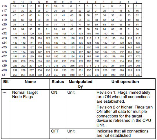
- If you need to monitor up to 255 Nodes you need to set a User defined area
- The Status Area can be changed to a User defined Area:
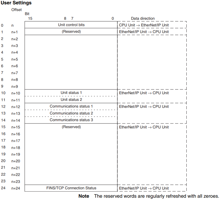
- When the layout of the allocated CIO Area words is set to user settings, the user settings area can be used in addition to the allocated CIO Area words
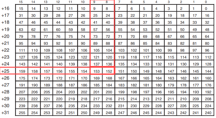
- Beginning word n = user defined area + (63)
- To view the flags of the connected Nodes (255) with the user settings, this will be located in the Normal Target Node Table (Ethernet/IP Unit to CPU Unit) (n+16 to n+31) :
Example:
In this example a CJ2M -EIP21 is communicating with two NX-EIC202 units. The Ethernet/IP is setup through our Network Configurator tool and the NX unit setup is done through Sysmac Studio.
-
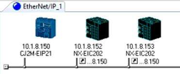 Unit 1 IP Address: 10.1.8.152
 - Unit 2 IP Address: 10.1.8.153
In this example using the Default layout would not display the Nodes 152 and 153 connection flags because the default layout has a Node limit set to 63.You could change the IP address to solve this but lets say we want to use the Node numbers higher that 63. How would we do that?
There are methods to solve this. Method 2 was used in this example.
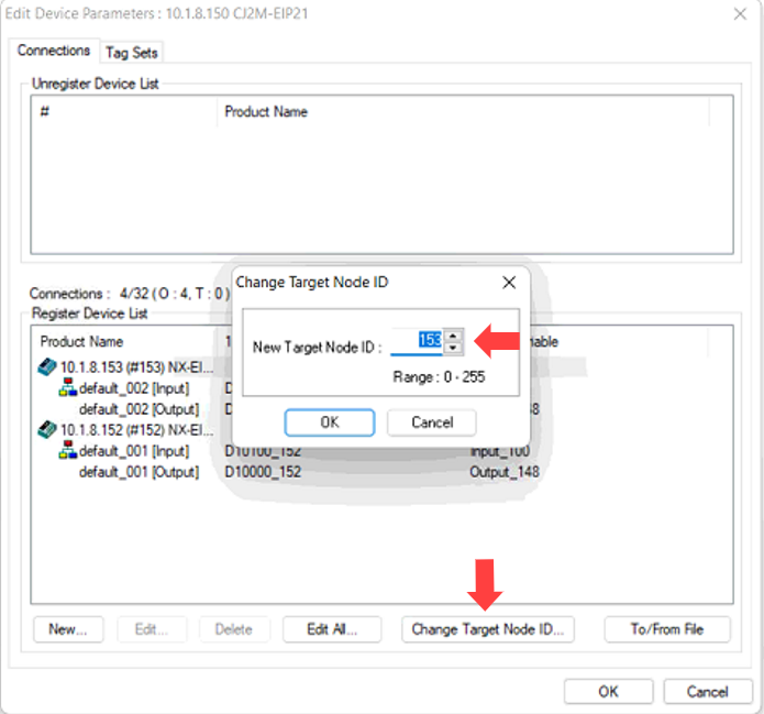
Method 1: Change the Unit Node ID in Network Configurator without changing the IP Address
- In your Network Configurator project >> Edit the device Parameters on the CPU
- Under the Connections >> Select the Connected Nodes and Select Change Target Node ID.
- Change the Node ID to any number between 0 - 63 . By Default this will match the last octet of the Unit IP Address
- Repeat this for all connected Units.
- When all Node ID have been Changed, download the changes to the network.
With a Node ID between 0 - 63
Under the CIO 1500 Area you will find the Connection Status of the Connected Nodes under the Normal Target Node Section beginning at n+20 - n+23.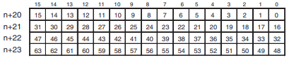
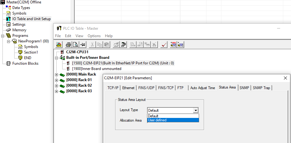
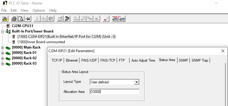
Method 2: In CX-Programmer, change the Status Area to User Defined.
- In CX- Programmer >> Select the IO table and Unit Setup >> Expand the Built-In Port/Inner Board >> Double Click on the CJ2M-EIPxx (Build in Ethernet/IP) >> Navigate to Status Area
- Change the Status Area to User Defined , this will setup a Custom Layout.
- Now specify a unused Memory area to view up to 255 Nodes.
- Transfer these settings to the Ethernet/IP card.
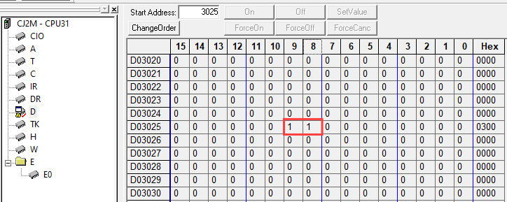
- D3025.08 = Node 152 (Unit 1 - 10.1.8.152) Connection flag
- D3025.09 = Node 153 (Unit 2 - 10.1.8.153) Connection flag
Delete
Resource Manual:
http://www.edata.omron.co.nz/eData/Networks/EIP/W465-E1-09.pdf