CORE SETUP PARAMETERS
Motor Nameplate Settings
- Hb102 - Set motor kW (0.01 to 160 kW)
- Hb103 - No of Motor Poles, (1500rpm = 4 poles, 3000rpm = 2 poles etc)
- Hb104 - Base frequency, (Motor Nameplate Freq, 10 to 590 Hz)
- Hb105 - Maximum frequency (Max Freq. 10 to 590 Hz)
- Hb108 – Rated Current, (motor Nameplate)
- AA121 – V/f Characteristics (Set to 00 or for V/f Constant Torque Control)
Motor Protection
- bC110 - Electronic thermal level, set to nameplate Amps
At this point the Motor is controlled from the Buttons on the front of the Drive.
CONTROL SETUP
Option A - 2 wire Control with External Ref
A101 - Main speed input source = 01 (Terminal)
AA111 – Run Command input source selection = 00 (FW/REV Terminal)
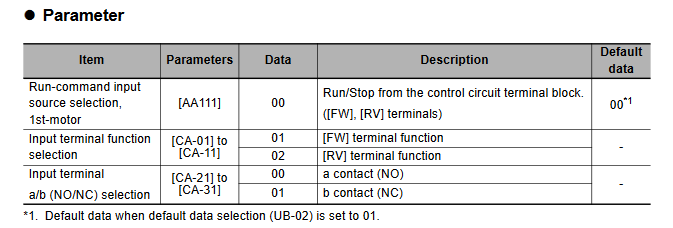
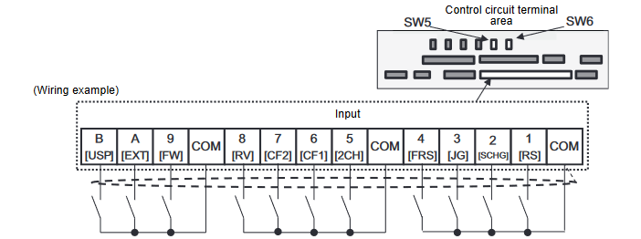
Option B – 3 wire Control with External Ref
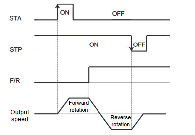
For 3-wire terminal commands, there are start, stop and forward/reverse operations. They are used to start and stop the inverter via an automatic reset contact such as a pushbutton switch.
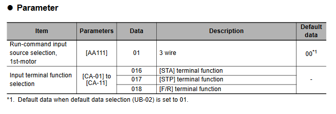
Operation start command can be given from [STA] terminal and stop command from [STP] terminal. To use the 3 wire function, the setting of the Run-command input source selection, 1st-motor [AA111] and the input terminal setting selection [CA-01]-[CA-11] needs to be changed.
Select [AA111]=01 3 wire function. In this example, the 3 wire function is assigned to the input terminal
function in the following way.

Operation can be started/stopped by making the 016 [STA]/017 [STP] terminal function ON/OFF on the
control circuit terminal block of the inverter.
018 [F/R] terminal function switches forward and reverse rotations by the contact.
The terminal action is made in the following way.
Useful Parameters
AC120 - Acceleration Time
AC122 - Deceleration Time
FA-01 - Main Speed reference monitor 0.00 to 590.00 (Hz)
AA101 - Main speed input source selection, 1st-motor
AA-12 - RUN-key Direction of LCD operator = 00 (Normal)/01 (Reverse rotation)
bb101 - Carrier Frequency (The electromagnetic noise from the motor, noise from the inverter and the heat generation in the inverter can be reduced/suppressed when you change the carrier frequency.)
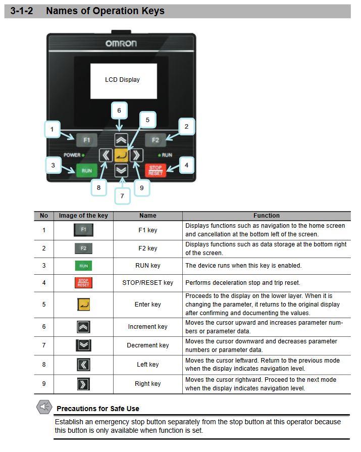
Key Description
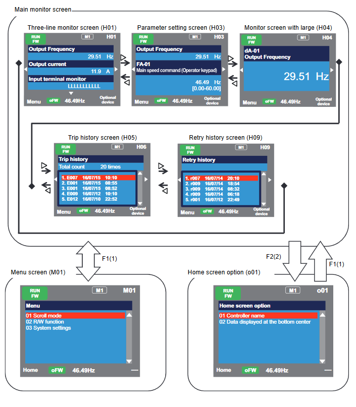
Screen Transition
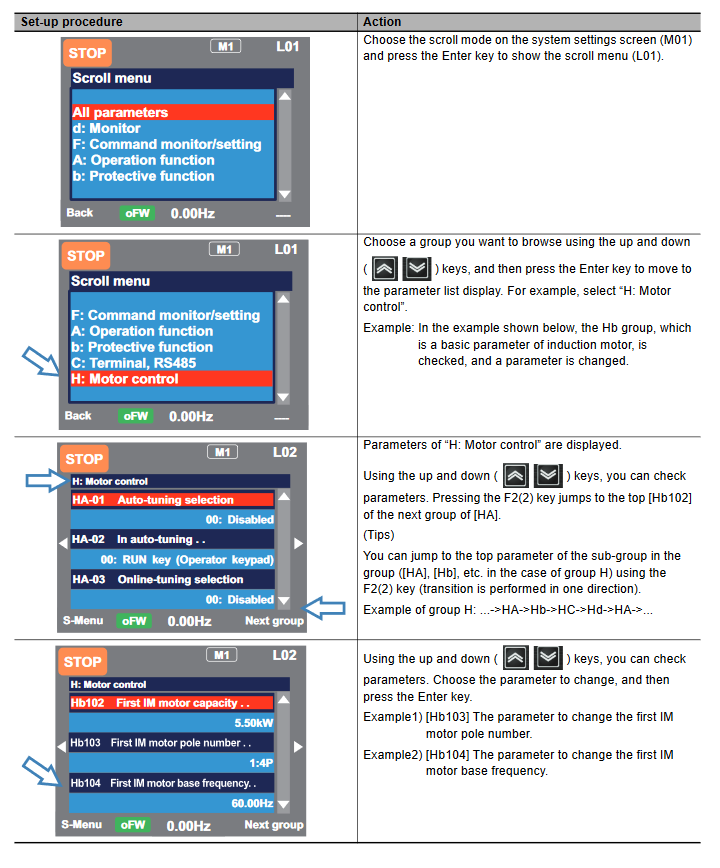
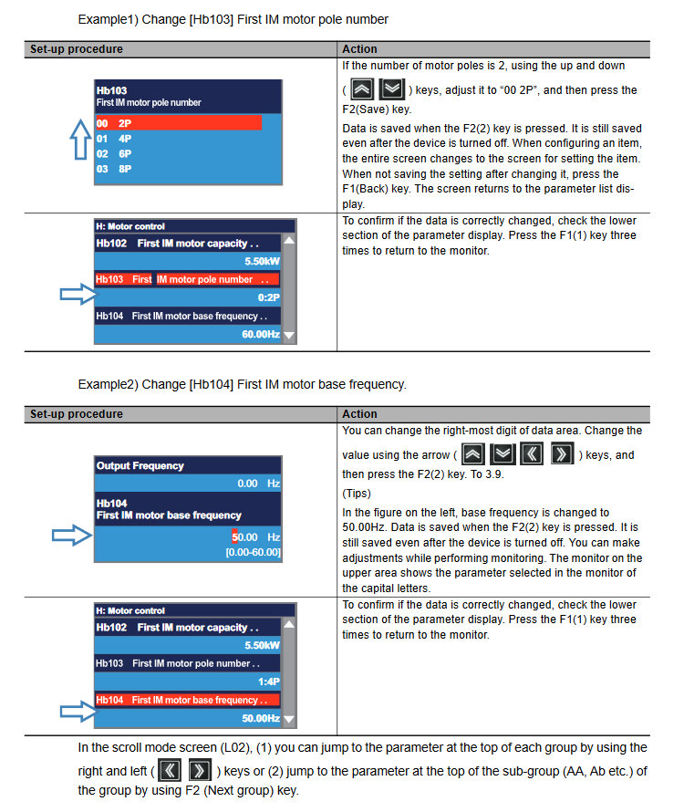
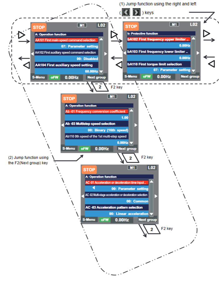
Setting Parameters
When configuring basic settings of motor, base frequency, rated voltage of motor, input and output of
terminals, as well as when configuring individual functions, change parameters in the scroll mode. You can check list of setting data of parameters in the scroll mode, therefore, it is also useful when checking the settings.
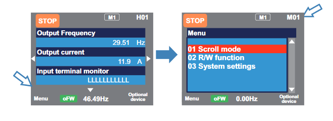
Press F1 (Menu) key on the screen that is displayed upon power-on (Multi-monitor in the example below) to move to the system settings screen (M01).
Factory Reset
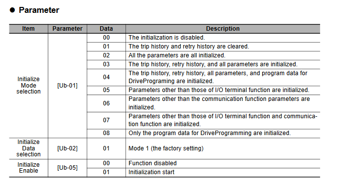
When the initialization target [Ub-01] is chosen and [Ub-05] Start Initialization is set to 01, the designated data can be initialized to the factory setting.
Only the trip history can be cleared without initialization of the stored parameter values.
To initialize the inverter, follow the steps below.
- Select initialization mode in [Ub-01].
- Set 01 in [Ub-05].
- The process is complete when “Initialization completed” is displayed.
Info
Duty type selection (Ub-03) is not initialized.
- The initialization sets the parameters to initial values. If the data before the initialization are necessary, read the data using the R/W function (Read) on the operator keypad or use PC software to save the data on a PC.
- The parameter for initialization is not displayed, depending on the setting of Display Restriction Selection (UA-10). Set the initial values to 00 (Full display) to complete the initialization.
- The initialization cannot be achieved when a change of the parameter setting values is banned on the setting of Soft Lock Selection (UA-16). Be sure to perform the initialization after the banned change of the parameter setting values is reset.
- Take a caution that the initialization starts when you set data of Initialize Enable (Ub-05) to 01 (Start initialization) and press F2 key. The previous data cannot be returned.