Connecting a Microscan Barcode Reader (QX-870) to an NJ/NX PLC
PLC to QX-870 Ethernet/IP Connection
Introduction
How to create a connection using Ethernet/IP between NJ/NX PLC and a Microscan Barcode Reader (QX-870).
Required Hardware and Software
Hardware:
• NJ/NX PLC and Power Supply
• Device to be connected (QX-870)
• Ethernet Switch/Router
• PC
• Ethernet Cables
Software:
• Sysmac Studio
• Microscan ESP
Files:
• EDS file for the device to be connected
Procedure
Install ESP
• Microscan ESP is used to configure the and program Microscan Readers.
• ESP Software can be found on the Omron Microscan Tools Drive that is packaged with the QX-870.
1. Follow the Prompts to install ESP from the Tools drive.
2. Click on the ESP icon to run the program.
• Refer to the QX-870 Industrial Raster Scanner User Manual for detailed information about using ESP to configure the QX-870.
Minimum System Requirements:
• 233 MHz Pentium PC
• Windows 8, 7, Vista, or XP operating system (32-bit or 64-bit)
• Internet Explorer 6.0 or higher
• 128 MB RAM or greater
• 160 MB free disk space
• 800 x 600 256 colour display (1024 x 768 32-bit colour recommended)
Physical Setup
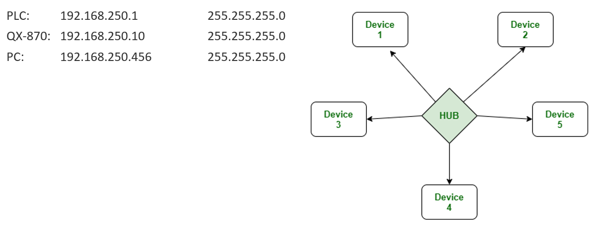
Connect the PLC, QX-870 and PC in a Star configuration and supply power to devices as needed. All devices need to be on the same network. For example, in this demonstration the settings are as follows:
On the PC: Sysmac Studio - Starting Up
Open Sysmac Studio and establish a connection to the PLC. Due to the network configuration, this should be done by selecting to connect using ‘Connect to Device’ followed by ‘Ethernet Connection via a hub ’. This will require entering the PLC’s IP address below this selection. For this example, the IP address of the NX1P2 was 192.168.250.1.
Good practice is to transfer the contents of the PLC to the PC and create a backup of those original contents.
Once the backup is created, load a blank program to Sysmac Studio. This can be done by closing the current program and starting a ‘New Project’. If you do this, ensure that you select the correct PLC.
On the PC: Sysmac Studio - EDS File
• Navigate to the menu at the top of the screen select 'Tools'->'Ethernet/IP Connection Setting’
• This opens the Ethernet/IP Device List page. On this page, double click on the PLC listed. Alternatively, right click and select ‘Edit’. This will open the Built In Ethernet/IP Port Settings Connection Settings page.
• Right click in the Toolbox in the upper right section of the screen, directly beneath ‘Target Device’. Select ‘Display EDS Library’.
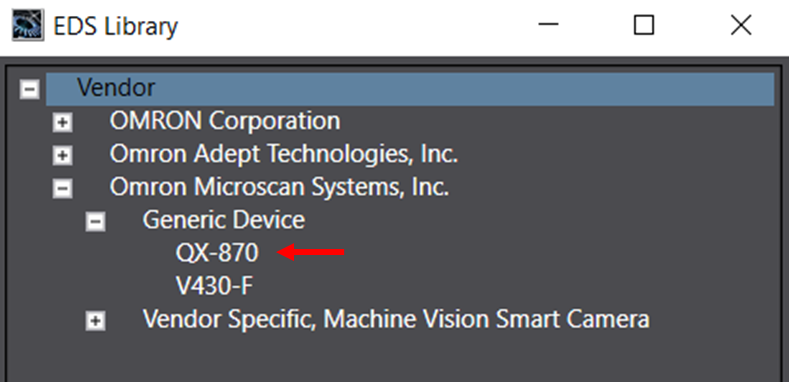
• In the pop-up window that appears, click the ‘Install’ button, browse to the appropriate EDS file for the QX-870, select it, and click ‘Open’.
• This will have added the QX-870 to the library, as shown to the right. The EDS window can now be closed.
Sysmac Studio: Data Structures
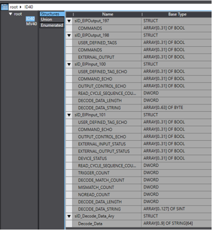
• Import the provided library by Omron which includes the data structures for QX-870 memory mapping. To install the library file, In the menu select projec->Library->Show References, then add the library by clicking on the + button, browsing to the provided .slr file in the PC.
• If you do not have the .slr file enter the Data Structures manually by selecting, in the 'Multiview Explorer', 'Programming'->'Data'->'Data Types' , right click in the space and select 'Create New Data Type' and enter the Structures in the image.
Sysmac Studio
• Use the Multiview Explorer on the left of the screen to navigate to Programming--> Data --> Global Variables. Select this page to bring up the table of global variables.
• Right click on the global variables and select ‘Create New’. Repeat this, so that there are two new global variables on the table.
• Name these two new variables appropriately and ensure that one is of the data type ‘sID_EIPInput_101’ and the other has the data type of ‘sID_EIPOutput_198’. In this example, we will name the two variables ‘ID_IN’ and ‘ID_OUT’
• For both of the new global variables, ensure that under the ‘Network Publish’ heading in the table, that ID_OUT is set to ‘Output’, while ID_IN is set to ‘Input’.

Sysmac Studio: Tag Sets
• Return to the Built In Ethernet/IP Port Settings Connection Settings page, and use the buttons on the left side of the page to ensure that the ‘Tag Set’ page is active.
• On this page, click on the button labelled ‘Registration All’, in the upper right. This brings up a window to confirm this operation. Check that the two previously created global variables are listed under Input and Output as appropriate, then click ‘Register’. This will create the tag sets for the connection, as shown below.


Sysmac Studio: Finalising the Ethernet/IP Settings
• Using the buttons on the left of the Built In Ethernet/IP Port Settings Connection Settings page, return to the Connection page. Now, we can select the appropriate Originator Variables, as shown in the below image.
• Following this selection, the Ethernet/IP settings on Sysmac Studio are complete. These must now be transferred to the PLC, using the ‘Transfer to PLC’ button in the lower right of the Built In Ethernet/IP Port Settings Connection Settings page.

Sysmac Studio: Verify Connection
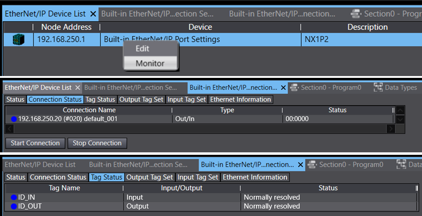
When the PLC is set to RUN mode, the EIP communication is started. Verify the connection status by monitoring the PLC status: in the 'Ethernet/IP Device List' right click on the PLC, then select 'monitor’. A good connection will look like the images below.
Sysmac Studio: Reading Data from the Barcode Reader to PLC
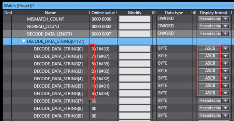
• Use the watch window to see the incoming data to the PLC from the reader by adding the relevant data structure to the window (ID_IN and ID_OUT).
• The incoming data from reader to PLC is in the ID_IN structure.
• The outgoing data from PLC to reader is in the ID_OUT structure.
• To view the Data obtained from reading a code, view the 'DECODE_DATA_STRING' array as shown below. Verify the code in front of the reader matches the results obtained by the reader.
• For better readability the display format can be changed to ASCII format.
Sysmac Studio: Example Program
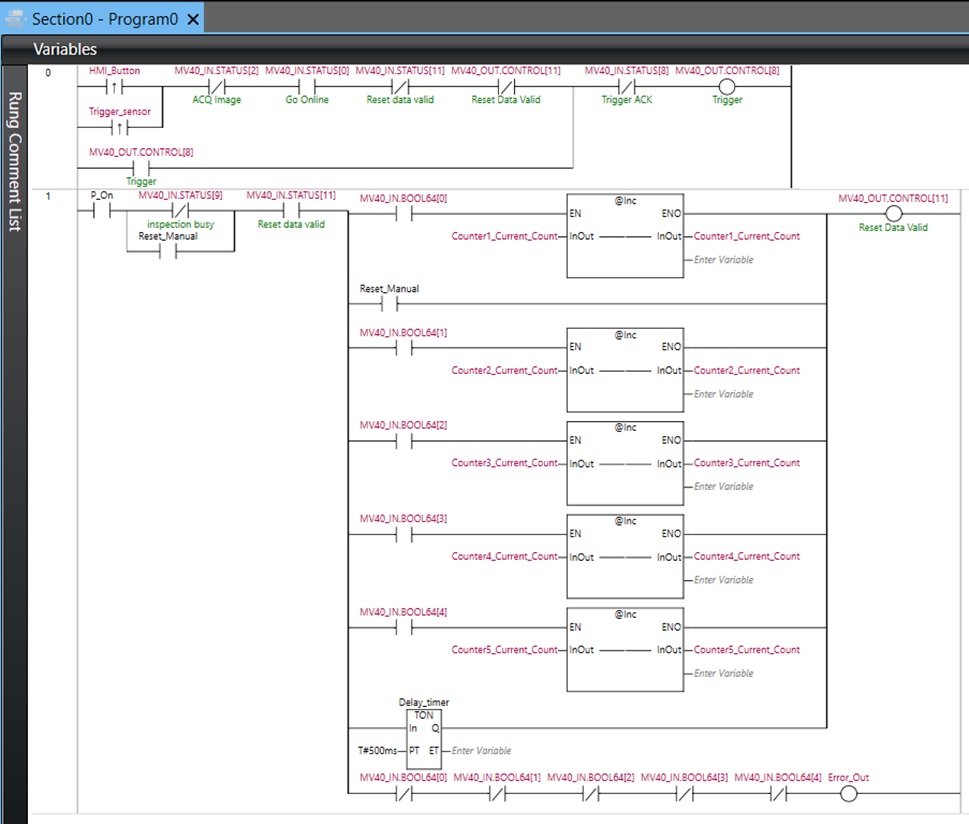
• Create a ladder program to control the QX-870. A sample program is shown in this image.
• The QX870_OUT and QX870_IN elements will register as global variables for this program.
• Once the ladder program is complete, connect to the PLC and transfer the program.
• Do not enable the transfer of Ethernet/IP settings at this stage.
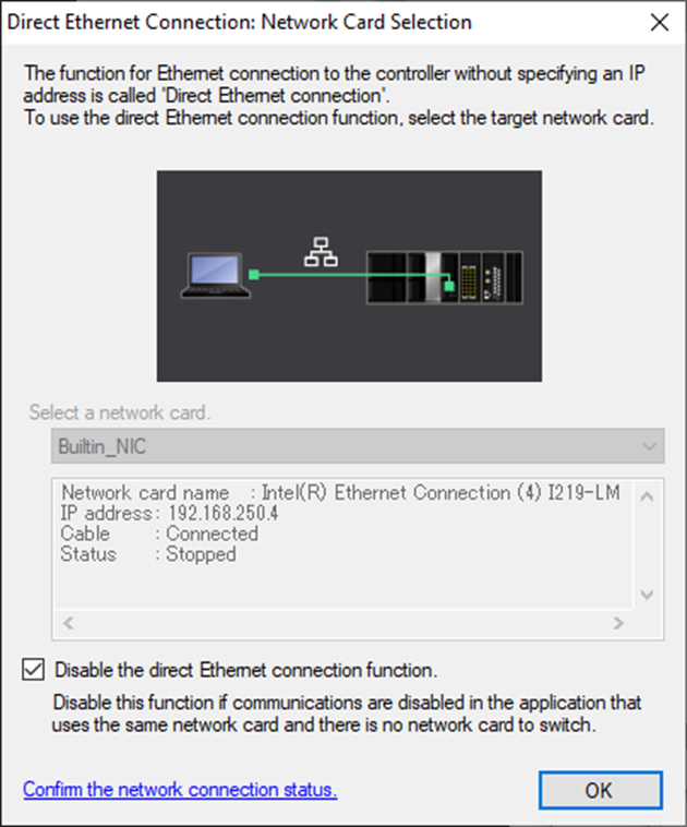
Appendix A: Direct Ethernet Utility Interface
• A connection issue can occur when AutoVISION is used to connect to a Microscan camera while the Direct Ethernet Connection is enabled.
• To resolve this, navigate in Windows Explorer to: “C:\ProgramData\Omron\Communications Middleware Utilities\StartMenu\Communications Middleware Utilities”, and open the shortcut named DirectEthernetUtility. Select ‘yes’ when prompted for administrator privileges.
• Check the box labelled ‘Disable the direct Ethernet connection function’ and click ‘OK’.
• Note that this process should be reversed if the Direct Ethernet Utility is required in the future.
