DeviceNet setup for CJ
Learn how to configure and troubleshoot DeviceNet networks for CJ industrial automation controllers.
Introduction
This guide goes over the basics of setting up basic remote IO over DeviceNet using a CJ1W-DRM21
Pre-Requisites
Hardware used in this example:
- CJ2M-CPU31
- CJ1W-DRM21
- DRT2-ID16-1 / OD16-1 DeviceNet Slaves
- PC setting:
- IP Address = 192.168.250.100
- Subnet = 255.255.255.0
Further Reading
This application note will be focus on specific aspect of the capability of the software/hardware and so if any further information on features / functions is needed such as wiring please refer to associated reference material.
CX-Integrator further reading
CX-Integrator is a Programming Device software package that enables reading the PLC's network and serial network configuration from a personal computer via an online connection. This enables easily performing many operations, such as monitoring the connection status of various networks, setting parameters, and diagnosing networks.
For the purpose of this application note we need to use CX-Integrator to set up a routing table
between our Ethernet PLC and the CJ1W-DRM21 for remote access/configuration without being
connected via serial to the PLC.
Routing tables register the paths to destination networks and the addresses for the nodes in FINS
communications. The routing tables are required when transferring data between networks by
message communications or other functions or switching the destination PLC in the network accessed from a Programming Device or ladder program instruction.
Routing tables consist of the following two tables.
- Local network table:
When two or more Communications Units are mounted in a single PLC, the CPU Unit uses
the local network table to identify the Communications Units and associated networks. The
local network table is required when two or more Communications Units are mounted in a
single PLC, or data will be transferred across network levels. - Relay network table:
When transferring data between networks, the relay network table indicates how to relay a
received message to reach the final destination node. The relay network table is required
when data will be transferred across network levels.
When more than one communication unit is mounted to a PLC. By default, the following applies: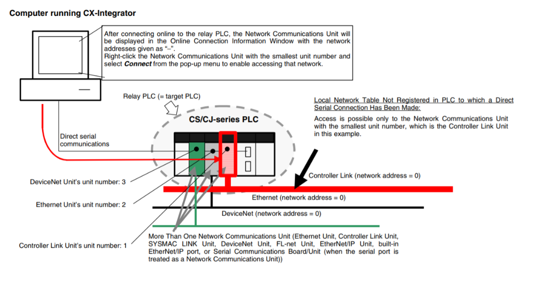
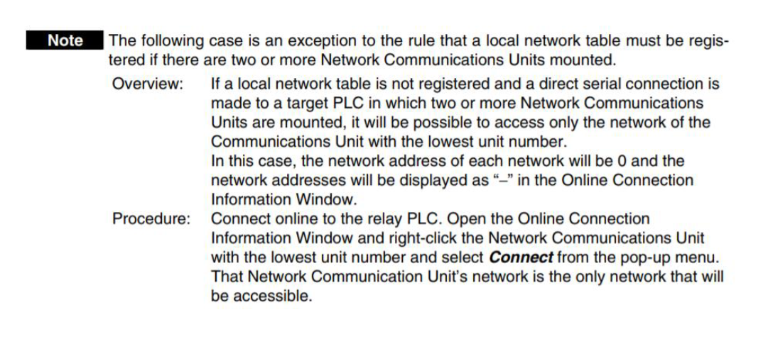 Note: A built-in Ethernet port on a PLC is classified as one communication unit
To use CX-Integrator, the computer must first connect online to a PLC connected through a direct serial/network connection or another PLC in the network (known as the relay PLC). Once the online connection is established with the relay PLC, another PLC can be specified as the target PLC and accessed through the relay PLC. Normally, the same PLC is both the relay PLC and the target PLC. In this case the relay PLC is the target PLC, where our equipment has a NJ301 (built-in Ethernet - first communication unit) and a CJ1W-DRM21 (DeviceNet - second communication unit)
Procedure
Step 1: Set node addresses
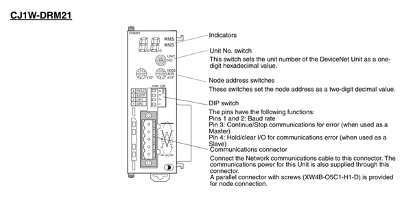
- The default unit no of CJ1W-DRM21 is 0 and node address is default of 63. However, these defaults won’t be used for this application note. We will use Node 1 for DRM21, Node 2 for Output module and node 3 for Input module. Rotate the dial to the desired position.
Note: The node address needs to be set to a value higher than 0 as this is a FINS network requirement for routing.
Step 2: Complete Network Connections
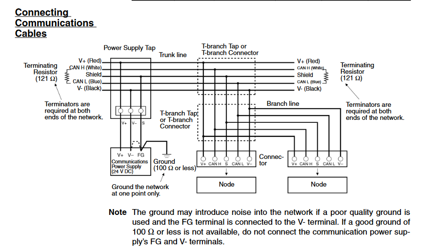
- Connect CJ-DRM21 and DeviceNet units together and power on the CPU rack and IO power supplies.
Step 3: Configure the PLC IO Table
- Open a new project in CX-Programmer and go online.
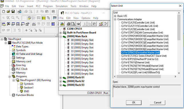
- Go to the IO table and unit setup, under main rack click on Empty slot based on the availability of your rack.
- Under Communication Adapter click on CJ1W-DRM21 (DeviceNet Master unit) and add it to the rack.
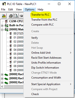
- Click on Option and transfer your settings to PLC. Make sure that the rotary nodes and units are correct on the units. In this example the unit no of the PLC is 0 and DRM unit no is 1.
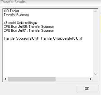
- Power cycle the CJ2.
Step 4: Creating a Routing Table
1. Launch CX-Integrator
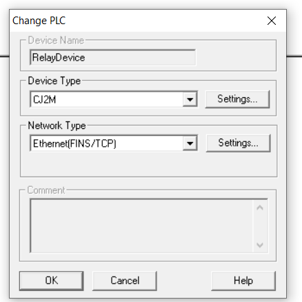
2. Go online with CX-Integrator using the following settings
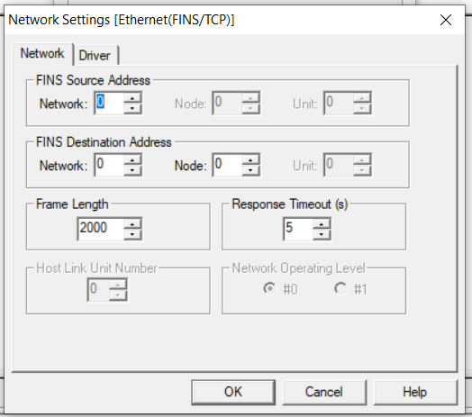
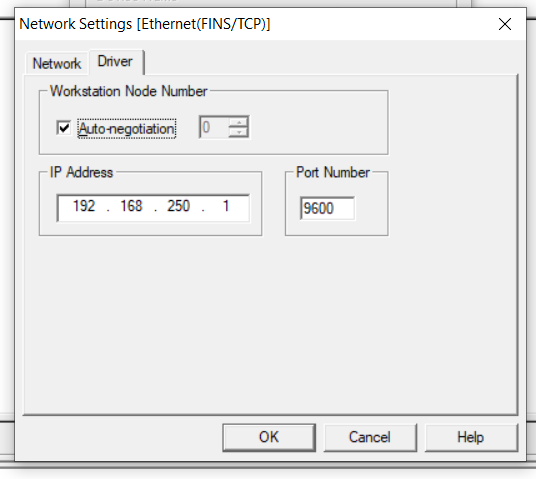
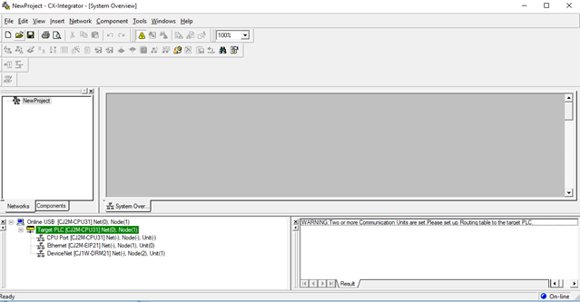
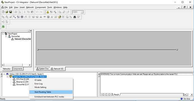
3. In order to create the Routing table and specify the networks, right click on target PLC and select Start Routing table
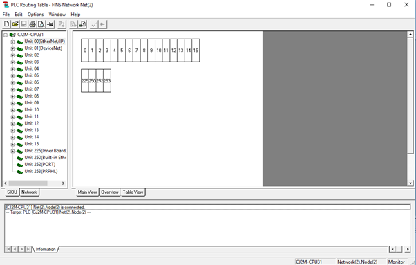
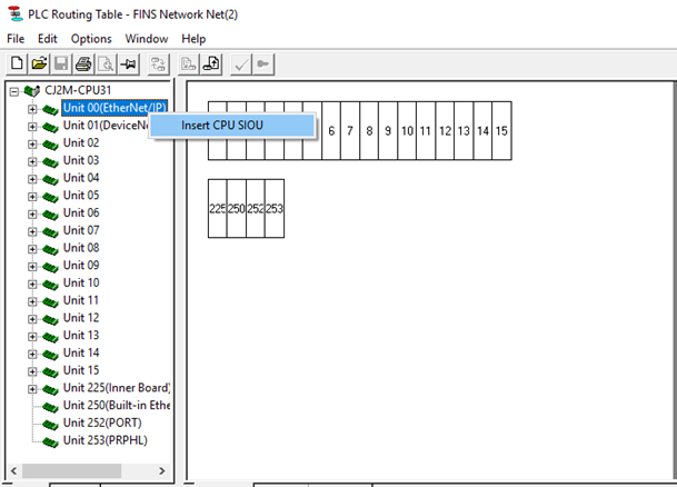
4. Under CJ2M-CPU31 right click on the Unit00(EtherNet IP) and select CPU SIOU. Set the network number to 1.
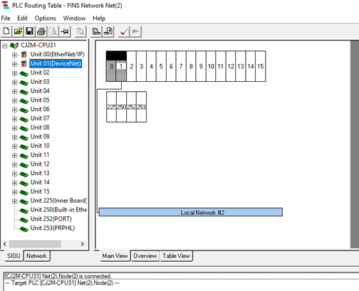
5. Right click on unit 01 (DeviceNet) and set the network number to 2.
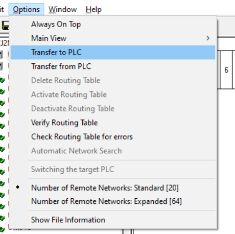
6. Once the routing table finished then click on option and select Transfer to PLC.
7. Once the transfer is complete return to the main window, and go offline.
8. Power cycle the CJ2Delete
Step 5: Register DeviceNet IO
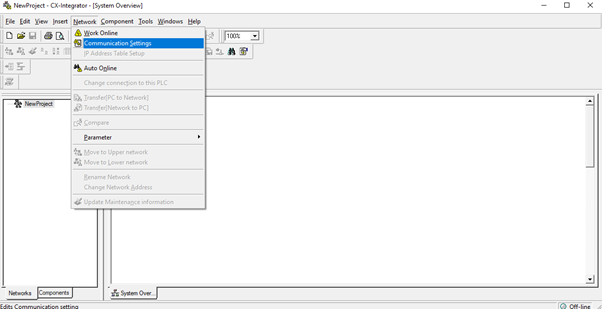
1. Under Network select Communication setting and configure the communication settings.
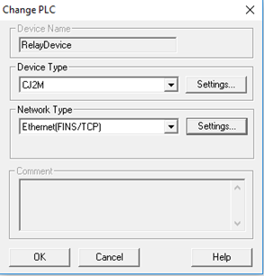
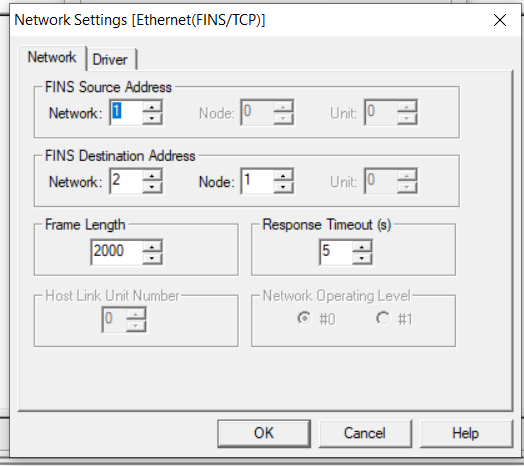
2. Set the FINS source address to 1. Set FINS destination address network to 2. Also set FINS destination node to the DRM21 rotary node which has been specified.
3. Go Online with CX-Integrator
4. Right click on DeviceNet and select Transfer[Network to PC] and click on transfer.
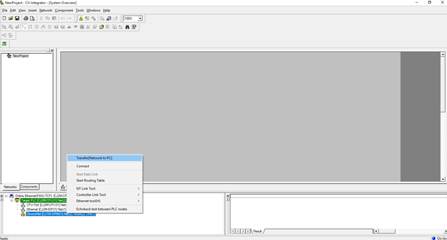
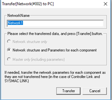
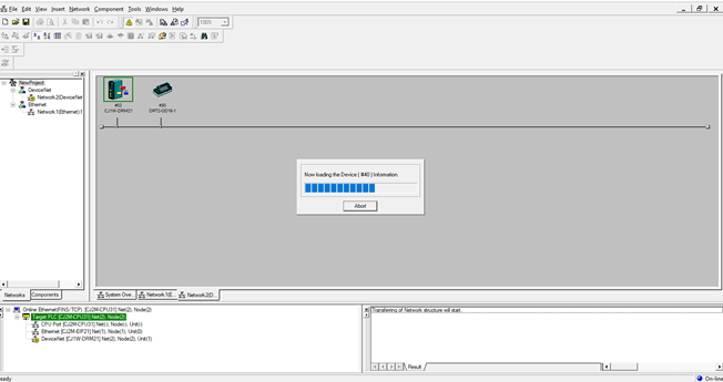
5. Once the transfer is done you can see the IO has been transferred on your DeviceNet Network rack.
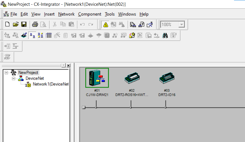
6. Go offline
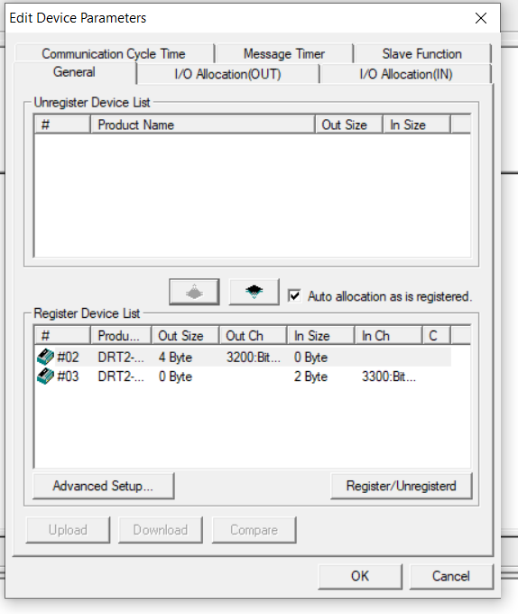
7. Double click the DRM21 module to bring up the edit paramereter window. Click the device register button to add both devices to the registered device list.
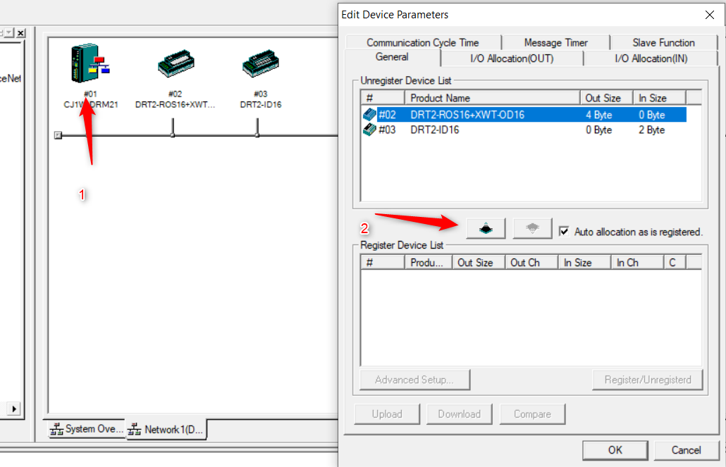
8. Go online in CX-Integrator
9. Transfer the network parameters
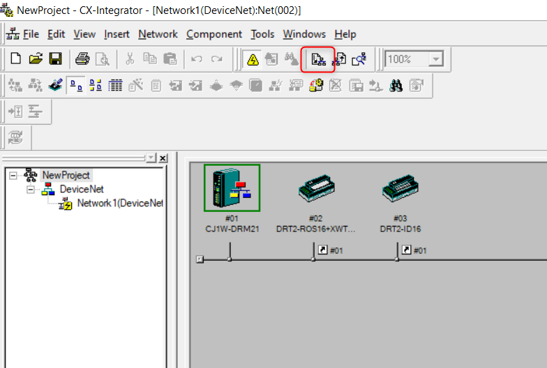
10. Double check that the connection is has been made, go online to the PLC with CX-Programmer and check that you can turn on the Input/Output. In this case our Output channels would start from 3200 bit 00.
Delete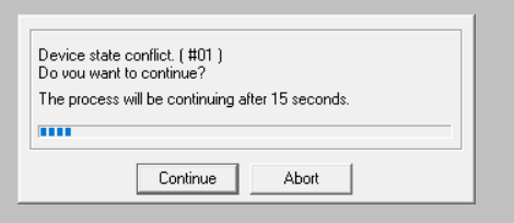 Set the mode by in CX-Programmer. Make sure that you have gone offline before going online again in CX-Integrator