NX to NX Communication using Ethernet/IP
Introduction
The purpose of this guide is to demonstrate the process of setting up a bi-directional Ethernet/IP connection between two NJ/NX PLC's. NX/NJ PLC's can only act as Originators, and cannot act as a target device. This means that we need to configure a Originator to Originator connection. The main difference between these is that an Originator to Originator only allows for read only connections between the devices.
Here's an example of an Originator → target connection -
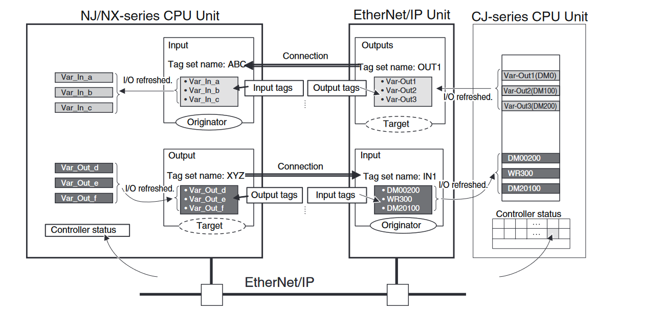
Note that there is two way communication with the Originator both reading and writing to the Target.
Here's an example of an Originator → Originator connection -
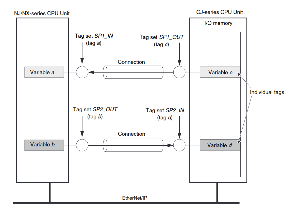
Note that we have still achieved a two way communication, but this time we had configure each PLC to read from the other. The NJ/NX initiates reading variable c into variable a and the CJ initiates reading variable b into variable d.
Info
The Devices used in this example have been pre-allocated two IP address. This example does not go through the configuration of the IP addresses.
PLC_1 is 192.168.250.1
PLC_2 is 192.168.250.2
Step 1 - Determine the tag sizes
The amount of data that can be sent or received from a PLC can vary according to what the user requires.
In this example, we will configure two sets of data structures that will be transmitted between the PLCs. Define both structures on both PLCs.
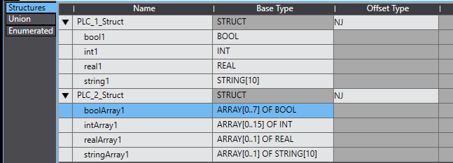
Step 2 - Create global variables
- Define global variables on PLC_1. Note the network publish types and variable types.

- Define global variables on PLC_2. Note the network publish types and variable types.

- Transfer your changes to the PLCs.
Step 4 - Create tag sets
On PLC_1:
Open the Ethernet/IP Connection settings window
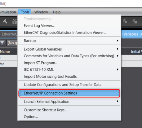
Choose the port you wish to edit and right click to choose "Edit".

Import the global variables to your tag sets by clicking "Registration All" and then register.
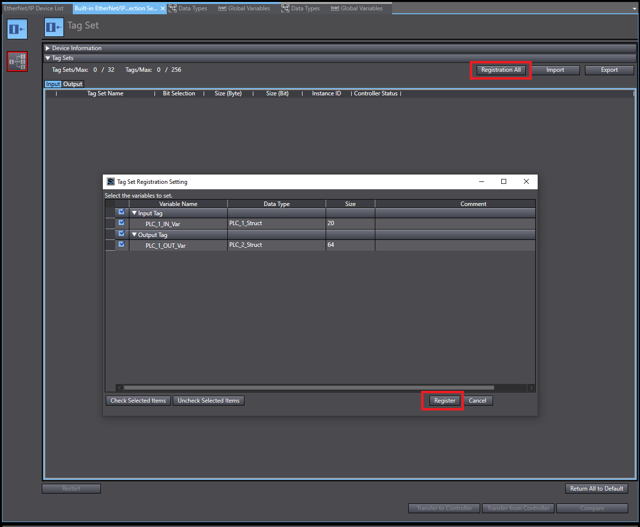
Repeat above for PLC_2
Step 5 - Create connections
On PLC_1:
Info
Steps 1 and 2 are not required if the two PLCs are in the same Sysmac project.
- Click the + icon to add the device.
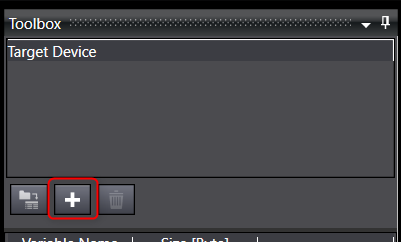
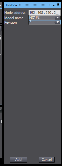
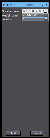
- Enter the Node address, Model Name and Revision then click Add.
- Navigate to the Connection window and click the + icon to add the connection.
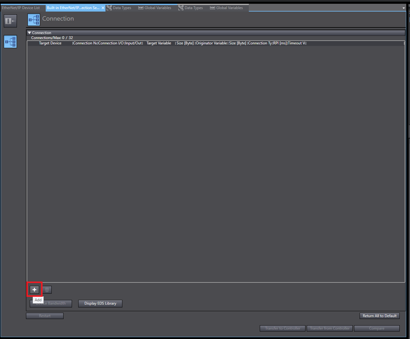
- Enter the details of the connection. Note that the Target variable is the output tag defined on PLC_2, and the output size matches the size of that tag.

- Transfer the connection settings by selecting Transfer to Controller.
On PLC_2:
- Click the + icon to add the device.

- Enter the Node address, Model Name and Revision then click Add.
- Navigate to the Connection window and click the + icon to add the connection.

- Enter the details of the connection. Note that the Target variable is the output tag defined on PLC_1, and the output size matches the size of that tag.

- Transfer the connection settings by selecting Transfer to Controller.