NX-EIC202 Ethernet/IP Setup Guide Using Sysmac

Written by Arlo D'Cruz
Updated at January 21st, 2026
Introduction
The purpose of this document is to demonstrate the process of setting up an Ethernet/IP network using Sysmac.
Configuration
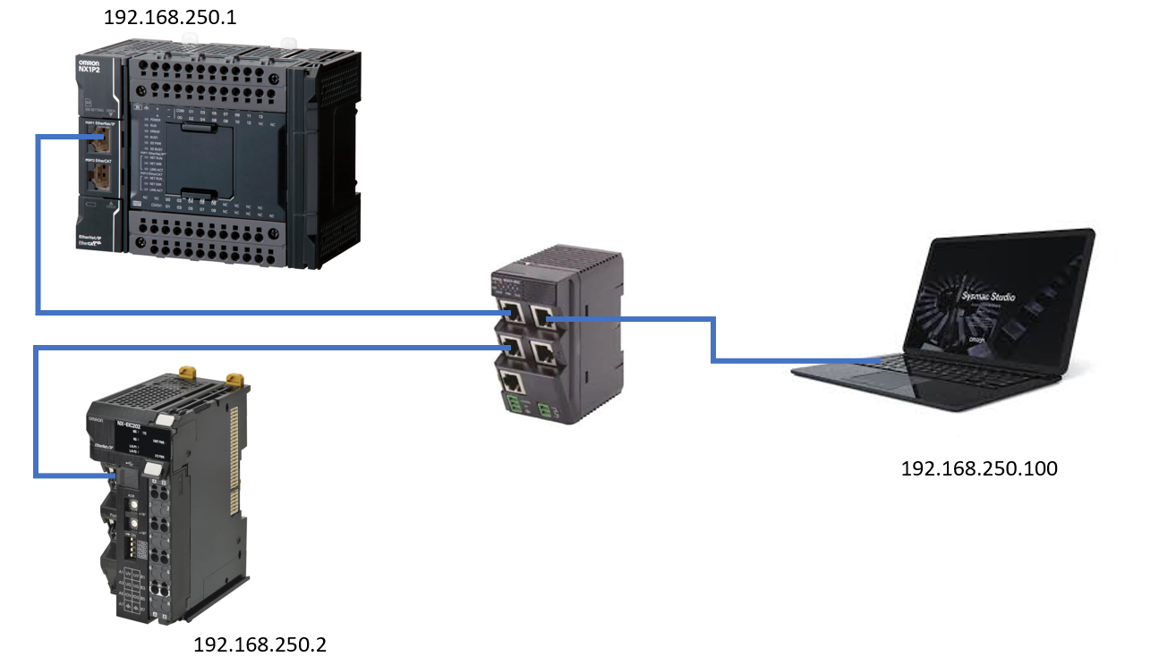
The following configuration was used:
 Procedure
Step 1 - Configuring the IP Address of the PC
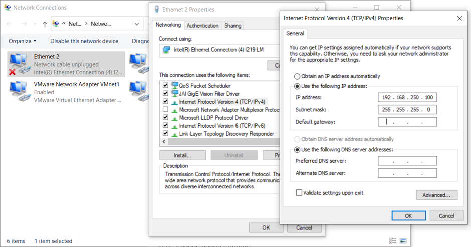
Change the IP address of the Ethernet port on the PC to the same subnet as the devices used.
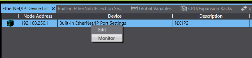
As seen above, the NX1P2 has an IP Address of 192.168.250.1 and the NX-EIC202 has an IP address of 192.168.250.2. Both of them have a subnet of 192.168.250.xx. Change the IP address of the PC so that it has the format of 192.168.250.xx where xx can be any number that is not 1 or 2. 100 was used below.
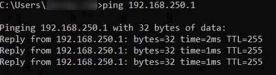
Next, check if the PLCs are showing up on the Network by going to the Command prompt.
 Type in the command "ping 192.168.250.1" to see if the PC can detect the NX1P2 through the Ethernet Port. The following shows the result where the PLC is present on the Network. Do this also for the NX-EIC202 on "192.168.250.2".
Step 2 - Determine tag sizes
Method 1 - Sysmac
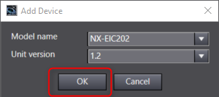
- Insert a coupler to your project.
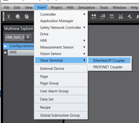
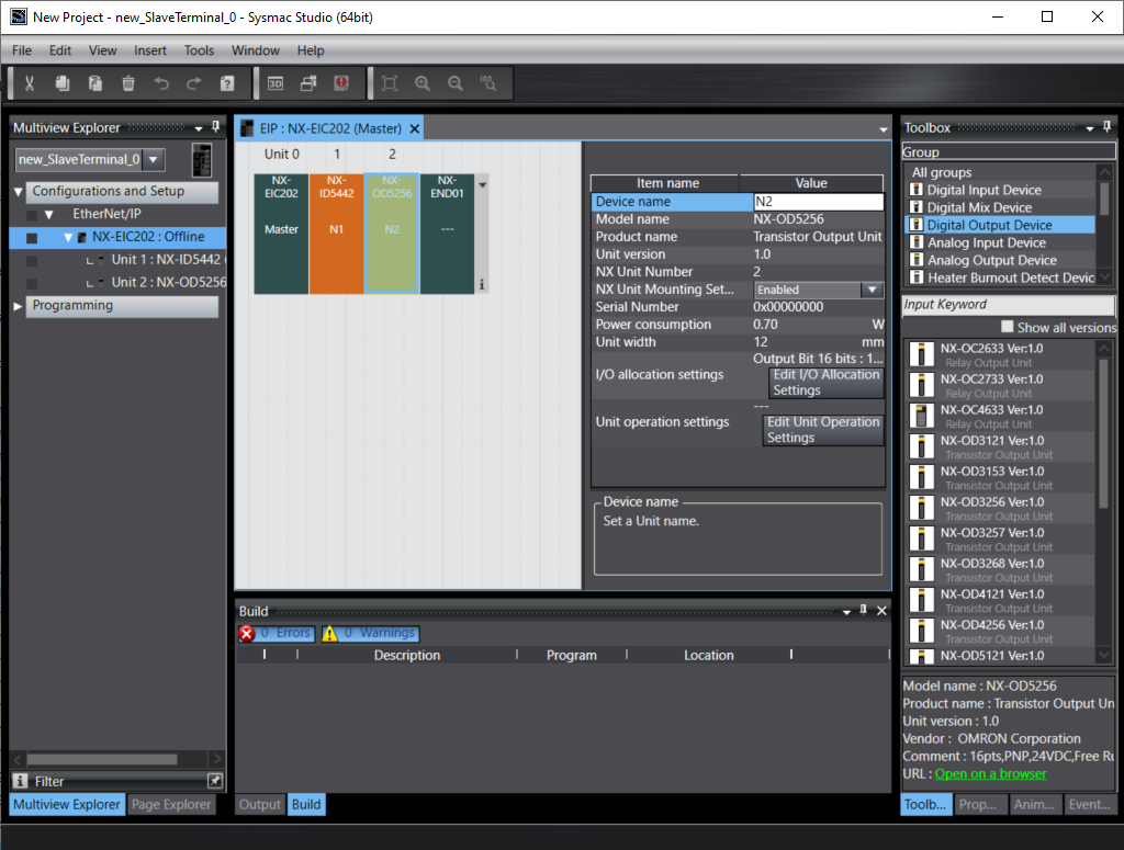
- Add the NX IO to match the physical configuration of the IO.
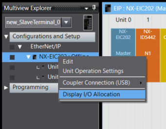
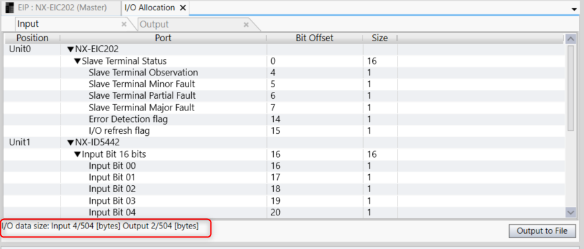
- Rick click the coupler in the Multiview Explorer to view the I/O Allocation.
- Make a note of the tag sizes. In this case we have 4 input bytes and 2 output bytes.

Method 2 - NX-IO Configurator
- Create a new project.
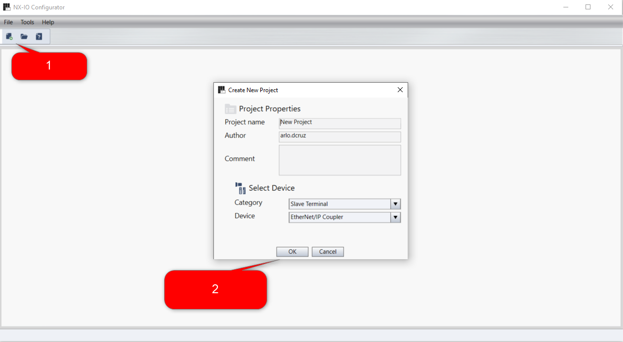
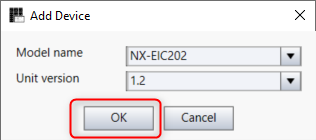
- Add the NX IO to match your coupler.
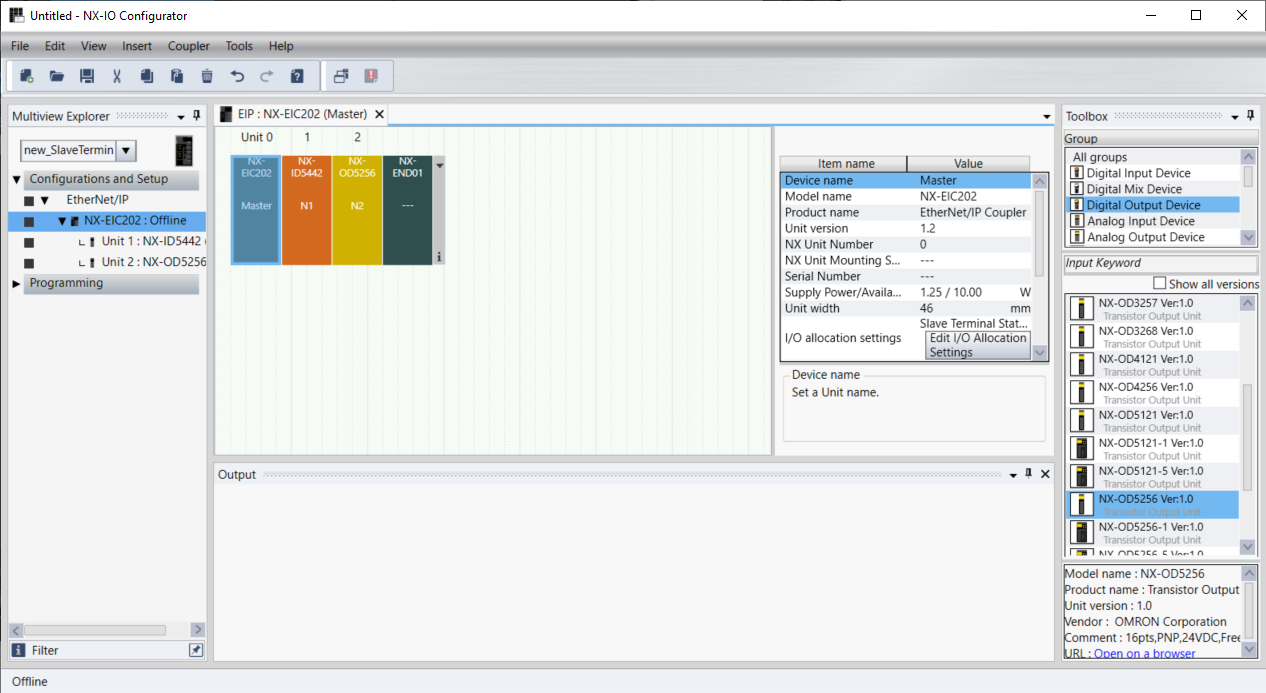
- Rick click the coupler in the Multiview Explorer to view the I/O Allocation.

- Make a note of the tag sizes. In this case we have 4 input bytes and 2 output bytes.
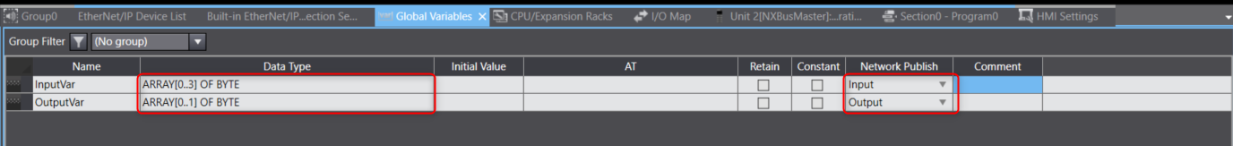
Step 3 - Create global variables
Create Input and Output type variables that match the IO size of the tags determined in Step 2.
Below is an example of creating Input/Output variables using basic byte arrays
 Below is an example of creating Input/Output variables using a data structure to automatically map the data.


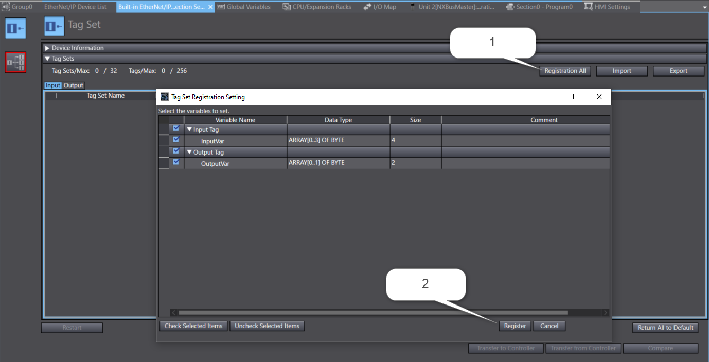
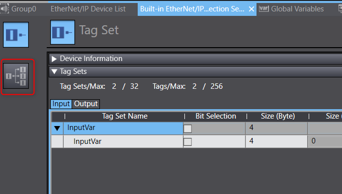
Step 4 - Create Tag sets
A tag is composed of one or more variables that is used to pass information to and from the Ethernet/IP master.
- Open the Ethernet/IP Connection settings window
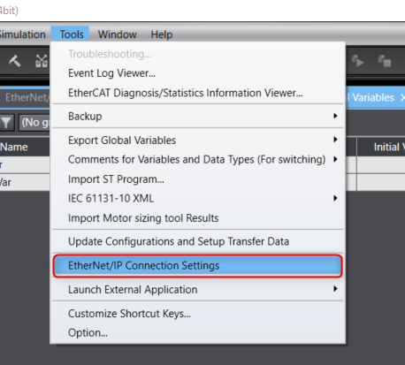
- Choose the port you wish to edit and right click to choose "Edit".

- Import the global variables to your tag sets by clicking "Registration All" and then register.
Step 5 - Create Connection
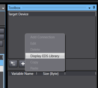
- Add the EDS file of the target device (Only required for 3rd party Ethernet/IP devices). Right click the Target Device menu in the Toolbox and select Display EDS Library.
 Click Install, navigate to the directory of you EDS and select the desired EDS.
 -

Click the + icon to add the device.

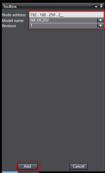
Enter the Node address, Model Name and Revision then click Add.
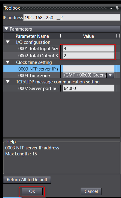
(Optional step depending on the target device, required for the NX-EIC202) Set the tag sizes of the target device. Right click the newly created device and select Edit.

Enter the sizes determined in Step 2 and click OK.
Go to the Connection window.
 Add a new Connection with the + button.
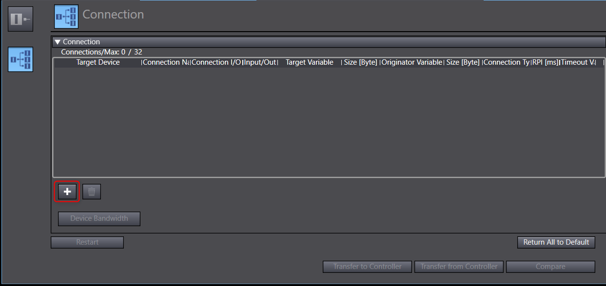
Set the target device.
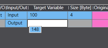
 In the Target Variable column, press Ctrl + Space to view available assemblies and choose the desired assembly.
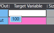

- Set the Originator variables using the dropdown menus.


- Go Online to the PLC and then Synchronize your changes. By default this will only transfer the global variables.
- Transfer the Ethernet/IP settings.
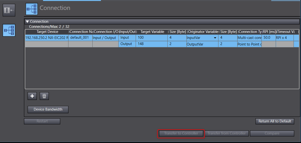
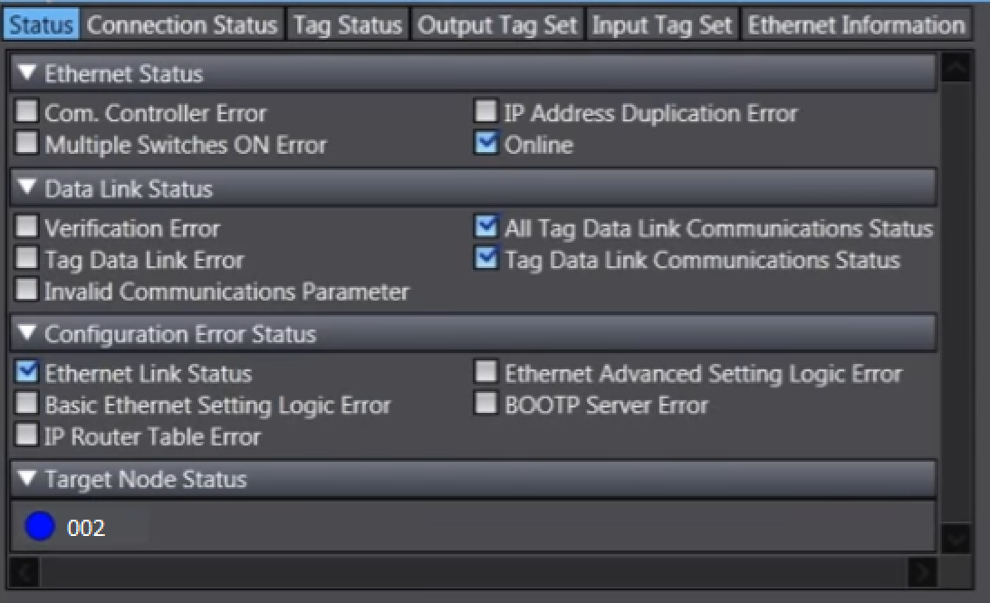
Now the Ethernet/IP configuration is complete, you can monitor the connection and check for errors.
 A blue circle indicates a successful connection.