Setting Heater Burnout Alarms on an E5CC/E5EC Temperature Controller
Introduction
The purpose of this step-by-step guide is to provide a clear method for setting heater burnout alarms on an E5CC or E5EC temperature controller.
A heater burnout alarm operates by detecting the current of the heater with a current transformer. If that current is detected as less than the specified heater burnout current, the temperature controller will assume that a heater burnout has occurred and output an alarm.
Note that a heater burnout alarm can only be used with a temperature controller that supports HS and HB alarm detection.
Procedure
Confirm that the heater burnout alarm is enabled
Step 1: Enter the Advanced Function Setting Level
Turn on the temperature controller.
Press both the level and mode buttons for at least 3 seconds to enter the Protect Level and display 'iCPt', which represents the Initial Setting/Communications Protect parameter. This parameter has a default value of 1.
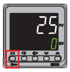
Note that the level button is labelled with a rectangle, and found in the location shown in the below image.

The mode button is located next to the level button, and is labelled with the following symbol.

Use the up and down arrow buttons to change the value of this parameter to 0.
Press both the level and mode buttons for at least 1 second to return to the Operation Level, before pressing the level button for at least 3 seconds to enter the initial setting level.
Press the mode button several times to display 'AMoV', which represents the Move to Advanced Function Setting Level parameter, which has a default value of 0.
Use the up and down arrow buttons to change the value of this parameter to -169. This will cause the temperature controller to enter the Advanced Function Setting Level, and display 'INIT'.
Step 2: Confirm the Heater Burnout Parameter's Value
Press the mode button several times to display 'HBU', which represents the Heater Burnout On/Off parameter. The default value of this parameter on temperature controllers that support the function is 'on'.
If the value of this parameter is 'off', use the up arrow button to change it to 'on', enabling the heater burnout alarm.
Check the destination of the output
Step 1: Remain in the Advanced Function Setting Level
If the temperature controller is not in the Advanced Function Setting Level, follow Step 1 from the previous section to enter it.
Step 2: Check the Output Destination
By default, the Heater Burnout alarm will be output on auxiliary output 1.
Press the mode button several times to display 'SUB1', which represents the auxiliary output 1 assignment parameter. This should have the value of 'HA', or 'Heater Alarm'.
If desired, use the mode button to navigate between the auxiliary output assignment parameters (represented by 'SUBx', where x is the number of the auxiliary output), and the up and down arrows to change their values, such that the Heater Burnout alarm will be output to the required auxiliary output.
Note that if the temperature controller supports both Heater Burnout and Heater Short alarm detection, a heater alarm is assigned by default to auxiliary output 1, as mentioned above. This alarm will output the logical OR of the Heater Burnout and Heater Short alarms.
Set the Heater Burnout Detection Current
Step 1: Enter the Adjustment Level
If the temperature controller is still in the Advanced Function Setting Level, press the level button for at least 1 second to return to the Initial Setting Level, then press the level button again for at least 1 second to return to the Operation Level.
Once in the Operation Level, press the level button for less than 1 second to display 'L.ADJ', which represents entering the Adjustment Level.
Step 2: Set the Detection Current Level
Press the mode button several times to display 'Hb1', which represents the Heater Burnout Detection 1 parameter. The default value of this parameter is 0.0 Amps.
Use the up and down arrow buttons to change the value of this parameter t the required value. Note that this parameter's unit of measurement is Amps.
This value is important to set correctly, and a value of 0 Amps is not always correct. See the below section on 'How to Calculate Heater Burnout Detection Current' for the calculation required to determine the correct value.
Once this value is set, return to the Operation Level or restart the temperature controller.
How to Calculate Heater Burnout Detection Current
The equation for this calculation is,

For example, a system uses three heaters, each rated at 200 V and 1 kW, connected in a parallel configuration.
The current through each heater is given by,
I = P/V
I = 1000 / 200 = 5 Amps
As the heaters are connected in parallel, the currents are summed to provide the total normal current, resulting in a normal current of 15 Amps.
In the case of a single heater burning out and therefore having 0 Amps of current through it, this configuration would have a total current of 10 Amps.
Substituting these values into the previous equation,
Heater Burnout Detection Current (HBDC) = (15 + 10) / 2
HBDC = 25/2 = 12.5 Amps
Therefore the appropriate Detection Current Level for this system is 12.5 Amps.
Delete